|
|
|
PDF V23990-P864-F49-PM Data sheet ( Hoja de datos )
| Número de pieza | V23990-P864-F49-PM | |
| Descripción | Power Integrated Module | |
| Fabricantes | Vincotech | |
| Logotipo | ||
Hay una vista previa y un enlace de descarga de V23990-P864-F49-PM (archivo pdf) en la parte inferior de esta página. Total 15 Páginas | ||
|
No Preview Available !
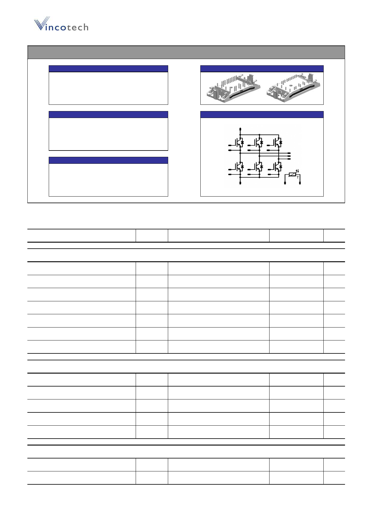
flowPACK 0 3rd gen
Features
Ɣ 2 clip housing in 12mm and 17mm height
Ɣ Trench Fieldstop IGBT3 technology
Ɣ Compact and low inductance design
Ɣ Built-in NTC
Target Applications
Ɣ Motor Drives
Ɣ Power Generation
Ɣ UPS
Types
Ɣ V23990-P864-F49-PM: 17mm height
Ɣ V23990-P864-F48-PM: 12mm height
V23990-P864-F49/F48-PM
preliminary datasheet
600V/30A
flow0 housing
Schematic
Tj=25°C, unless otherwise specified
Parameter
Maximum Ratings
Symbol
Condition
Value
Unit
Inverter Transistor
Collector-emitter voltage
VCE
600
DC collector current
Repetitive peak collector current
IC
ICpulse
Tj=Tjmax
tp limited by Tjmax
Th=80°C
Tc=80°C
31
90
Power dissipation per IGBT
Gate-emitter peak voltage
Ptot
VGE
Tj=Tjmax
Th=80°C
Tc=80°C
60
±20
Short circuit ratings*
Maximum Junction Temperature
tSC
VCC
Tjmax
Tj150°C
VGE=15V
6
360
175
* It is recommended to not exceed 1000 short circuit situations in the lifetime of the module and to allow at least 1s between short circuits
Inverter Diode
Peak Repetitive Reverse Voltage
DC forward current
Repetitive peak forward current
Power dissipation per Diode
Maximum Junction Temperature
VRRM
IF
IFRM
Ptot
Tjmax
Tj=25°C
Tj=Tjmax
tp limited by Tjmax
Tj=Tjmax
Th=80°C
Tc=80°C
Th=80°C
Tc=80°C
600
30
60
46
175
V
A
A
W
V
ȝs
V
°C
V
A
A
W
°C
Thermal properties
Storage temperature
Operation junction temperature
Tstg
Top
-40…..+125
-40…..+Tjmax-25
°C
°C
copyright Vincotech
1
Revision: 1
1 page 
Output Inverter
V23990-P864-F49/F48-PM
preliminary datasheet
Figure 5
Typical switching energy losses
as a function of collector current
E = f(IC)
1,8
1,5
1,2
0,9
0,6
0,3
0
0 10
inductive load
Tj =
VCE =
VGE =
Rgon =
Rgoff =
25/150
300
±15
16
16
20
°C
V
V
ȍ
ȍ
30
Figure 7
Typical reverse recovery energy loss
as a function of collector current
Erec = f(IC)
1
0,8
Output inverter IGBT
Eoff Eon
Eoff
Eon:
40 50 I C (A) 60
Figure 6
Typical switching energy losses
as a function of gate resistor
E = f(RG)
1,8
1,5
1,2
0,9
0,6
0,3
0
0 15 30
inductive load
Tj =
VCE =
VGE =
IC =
25/150
300
±15
30
°C
V
V
A
Output inverter IGBT
Eon
Eon
Eoff
Eoff
45 60 R G( Ω ) 75
Output inverter IGBT
Erec
Figure 8
Typical reverse recovery energy loss
as a function of gate resistor
Erec = f(RG)
1
0,8
Output inverter IGBT
0,6 0,6
Erec
0,4 0,4
Erec
0,2 0,2 Erec
0
0 10 20 30 40 50 I C (A) 60
0
0 15 30 45 60 R G( Ω ) 75
inductive load
Tj =
VCE =
VGE =
Rgon =
25/150
300
±15
16
°C
V
V
ȍ
inductive load
Tj =
VCE =
VGE =
IC =
25/150
300
±15
30
°C
V
V
A
copyright Vincotech
5
Revision: 1
5 Page 
V23990-P864-F49/F48-PM
preliminary datasheet
Switching Definitions Output Inverter
General conditions
Tj
Rgon
Rgoff
= 150 °C
= 16 ȍ
= 16 ȍ
Figure 1
Output inverter IGBT
Turn-off Switching Waveforms & definition of tdoff, tEoff
(tEoff = integrating time for Eoff)
140
120
100
80
Uge 90%
tdoff
Uce 90%
Uce
60
%
40
Ic
tEoff
20
Ic 1%
0
Uge
-20
-40
-0,1
0
VGE (0%) =
VGE (100%) =
VC (100%) =
IC (100%) =
tdoff =
tEoff =
0,1 0,2 0,3 0,4 0,5 0,6 0,7
time (us)
-15 V
15 V
300 V
30 A
0,17 ȝs
0,45 ȝs
Figure 2
Output inverter IGBT
Turn-on Switching Waveforms & definition of tdon, tEon
(tEon = integrating time for Eon)
240
Ic
200
160
120 Uce
%
80
40
0
-40
2,7
2,8
VGE (0%) =
VGE (100%) =
VC (100%) =
IC (100%) =
tdon =
tEon =
tdon
Uge
Uge10%
2,9 3
-15
15
300
30
0,10
0,26
Ic10%
Uce3%
tEon
tim3,e1(us) 3,2
V
V
V
A
ȝs
ȝs
3,3
3,4
3,5
Figure 3
Turn-off Switching Waveforms & definition of tf
140
Output inverter IGBT
120
IC
100
80
fitted
Ic 90%
Uce
%60
Ic 60%
40 Ic 40%
20
Ic10%
0 tf
Figure 4
Turn-on Switching Waveforms & definition of tr
240
Output inverter IGBT
200
160
120
%
80
Uce
40
Ic
0
Ic90%
tr
Ic10%
-20
0,1 0,15 0,2 0,25 0,3 0,35 0,4 0,45
time (us)
-40
3
3,05 3,1 3,15 3,2 3,25
time(us)
VC (100%) =
IC (100%) =
tf =
300 V
30 A
0,11 ȝs
VC (100%) =
IC (100%) =
tr =
300 V
30 A
0,02 ȝs
copyright Vincotech
11
Revision: 1
11 Page | ||
| Páginas | Total 15 Páginas | |
| PDF Descargar | [ Datasheet V23990-P864-F49-PM.PDF ] | |
Hoja de datos destacado
| Número de pieza | Descripción | Fabricantes |
| V23990-P864-F49-PM | Power Integrated Module | Vincotech |
| Número de pieza | Descripción | Fabricantes |
| SLA6805M | High Voltage 3 phase Motor Driver IC. |
Sanken |
| SDC1742 | 12- and 14-Bit Hybrid Synchro / Resolver-to-Digital Converters. |
Analog Devices |
|
DataSheet.es es una pagina web que funciona como un repositorio de manuales o hoja de datos de muchos de los productos más populares, |
| DataSheet.es | 2020 | Privacy Policy | Contacto | Buscar |