|
|
|
PDF GP1F351T Data sheet ( Hoja de datos )
| Número de pieza | GP1F351T | |
| Descripción | Optical Mini-Jack for Digital Audio Equipment | |
| Fabricantes | Sharp Electrionic Components | |
| Logotipo | ||
Hay una vista previa y un enlace de descarga de GP1F351T (archivo pdf) en la parte inferior de esta página. Total 7 Páginas | ||
|
No Preview Available !
GP1F351T/GP1F351R
s Features
1. Electric and optical signal compatible design
( Three kinds of terminals are
integrated into a single unit).
2. Compact design with small jack
compatible mini-plug
( Less than 1/2 in volume of GP1F32T/R )
3. OPIC type
( Direct interface to microcomputer
of the I/O signals )
( High fidelity real sound reproduction)
4. High speed data transmission
Signal transmisson speed: MAX. 8Mbps
( NRZ signal )
s Applications
1. MD, DCC
2. Portable CD, DAT
GP1F351T/GP1F351R
Optical Mini-Jack for Digital
Audio Equipment
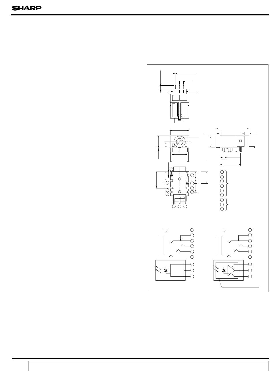
s Outline Dimensions
3 - 0.5
2.54 2.54
7.2
(Unit : mm)
10 2.5
φ 3.6
18.1
2.8
3.7 3.7
9.65
8 - 1.0
11.0
4
5
36
2
1
2
1
789
1
2
3
4
Jack terminal
5
6
7
8 Device terminal
9
Jack terminal configuration
GP1F351T
GP1F351R
LED
Drive
IC
1
4
6
2
3
5
8 Vcc
7 Vin
9 GND
1
4
6
2
3
5
7 Vcc
9 Vout
8 GND
OPIC light detector
∗ OPIC is a trademark of Sharp and stands for Optical IC.
It has light detecting element and signal processing circuitry
integrated single chip.
“ In the absence of confirmation by device specification sheets, SHARP takes no responsibility for any defects that occur in equipment using any of SHARP's devices, shown in catalogs,
data books, etc. Contact SHARP in order to obtain the latest version of the device specification sheets before using any SHARP's device.”
1 page 
GP1F351T/GP1F351R
Test item
Test time
Low→High pulse delay time
High→Low pulse delay time
Pulse width distortion
Low→High Jitter
High→Low Jitter
Symbol
t PLH
t PHL
∆ tw
∆ tjr
∆ tjf
Test condition
-
∆ tw= t PHL- t PLH
-
Set the trigger on the rise of input signal
to measure the jitter of the rise of output
Set the trigger on the fall of input signal
to measure the jitter of the fall of output
Note) ( 1) The waveform write time shall be 4 seconds. But do not allow the waveform to be distorted by incresing
the brightness too much.
( 2) VCC = 5.0 ±0.05V ( State of operating)
( 3) The probe for the oscilloscope must be more than 1MΩ and less than 10pF.
Fig. 4 Supply Current
Supply voltage
Optical output
coupling fiber
Standard transmitter input signal
Input conditions
VCC = 5.0 ± 0.05V
PC = -14.5dBm
6Mbps NRZ, Duty 50% or 3Mbps
biphase mark PRBS signal
Measuring method
Measured on an
ammeter
( DC average
amperage )
Standard
transmitter
Vin Vcc GND
Input
5V
fiber optic cable
GP1F351R
Unit to be measured
Vcc GND Vout
Vcc
A
Ammeter
Fig. 5 Measuring Method of Output Voltage and Pulse Response
Standard
transmitter
Vin Vcc
GND
5V
Input
6Mbp/s NRZ, duty 50%
fiber optic cable
GP1F351R
Unit to be measured
Vcc GND Vout
Vcc Rso
CH1
CH2
Rsi
Tektronix 7834
or 7934 type
Oscilloscope
5 Page | ||
| Páginas | Total 7 Páginas | |
| PDF Descargar | [ Datasheet GP1F351T.PDF ] | |
Hoja de datos destacado
| Número de pieza | Descripción | Fabricantes |
| GP1F351R | Optical Mini-Jack for Digital Audio Equipment | Sharp Electrionic Components |
| GP1F351T | Optical Mini-Jack for Digital Audio Equipment | Sharp Electrionic Components |
| Número de pieza | Descripción | Fabricantes |
| SLA6805M | High Voltage 3 phase Motor Driver IC. |
Sanken |
| SDC1742 | 12- and 14-Bit Hybrid Synchro / Resolver-to-Digital Converters. |
Analog Devices |
|
DataSheet.es es una pagina web que funciona como un repositorio de manuales o hoja de datos de muchos de los productos más populares, |
| DataSheet.es | 2020 | Privacy Policy | Contacto | Buscar |