|
|
|
PDF GP1020 Data sheet ( Hoja de datos )
| Número de pieza | GP1020 | |
| Descripción | SIX-CHANNEL PARALLEL CORRELATOR CIRCUIT FOR GPS OR GLONASS RECEIVERS | |
| Fabricantes | Zarlink Semiconductor Inc | |
| Logotipo | ||
Hay una vista previa y un enlace de descarga de GP1020 (archivo pdf) en la parte inferior de esta página. Total 30 Páginas | ||
|
No Preview Available !
FEBRUARY 1994
DS3605-2.2
GP1020
SIX-CHANNEL PARALLEL CORRELATOR CIRCUIT
FOR GPS OR GLONASS RECEIVERS
The GP1020 is a six-channel CMOS digital correlator which
has been designed to work with the GP1010 L1-channel down-
converter or other integrated circuits, and may be used to acquire
and track the GPS C/A code or the GLONASS signals.
For each of the six channels the GP1020 includes independ-
ent digital down-conversion to baseband, C/A code generation,
correlation, and accumulate-and-dump registers.
The GP1020 interfaces with a microprocessor via a 16-bit
data bus to control the acquisition and tracking processes using
the various registers on the chip.
FEATURES
s Six Fully Independent Correlation Channels
s Switchable to Receive GPS or GLONASS Codes
s Input Multiplexer for Multiple GPS Front-Ends – Allows
Antenna Diversity
s Input Multiplexer for GLONASS Multiple (Separate
Channels) Front-Ends
s Digital Interface Compatible with Most 16 or 32-Bit
Microprocessors
s Fully Compatible with GP1010 GPS Receiver Front-End
s Sideways Stackable to give Multiples of Six Channels
s 120-pin Plastic Quad Flatpack
s Power Dissipation Less Than 500mW
APPLICATIONS
s GPS or GLONASS Navigation Systems
s High Integrity Combined Receivers
s GPS Geodetic Receivers
s GPS Time Reference
ORDERING INFORMATION
The GP1020 is available in 120-pin Quad Flatpacks (Gullwing
formed leads) in both Commercial (0°C to 170°C) and Industrial
(240°C to 185°C) grades. The ordering codes below are for
standard screened devices.
ORDERING CODES
GP1020 CG GPKR Commercial - Plastic 120-pin QFP (GP120)
GP1020 IG GPKR Industrial - Plastic 120-pin QFP (GP120)
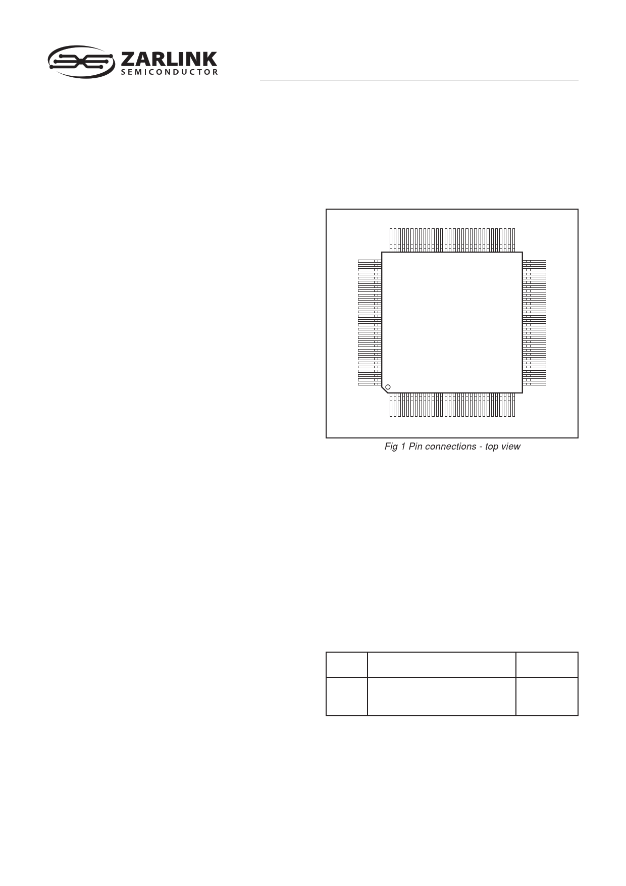
90
91
61
60
GP1020
120 31
1 30 GP120
Fig 1 Pin connections - top view
ABSOLUTE MAXIMUM RATINGS
These are not the operating conditions, but are the absolute
limits which if exceeded, even momentarily, may cause perma-
nent damage. To ensure sustained correct operation the device
should be used within the limits given under Electrical Character-
istics.
Supply voltage (VDD) from ground (VSS):
20·3V to16·0 V
Input voltage (any input pin):
VSS20·3V to VDD10·3 V
Output voltage (any output pin):
VSS20·3V to VDD10·3 V
Storage temperature:
255°C to 1125°C
RELATED PRODUCTS
Part
Description
DW9255 35·42MHz SAW Filter
GP1010 GPS Receiver Front-End
Datasheet
Reference
DS3861
DS3076
1 page 
TIMING CHARACTERISTICS (See Figs. 4 to 9)
Characteristic
Symbol
Value
Units
Min. Max.
Address hold time
ALE pulse width
ALE valid to WEN or RW valid (WPROG = 1)
ALE valid to WEN or RW valid (WPROG = 0)
Address valid to ALE low
Address valid to WEN or RW valid
CS high to ALE valid
CS low to WEN or RW valid
Data hold time
Data setup time
RW high to data at high impedance
RW valid to data valid
RW valid to WEN high
WEN low to RW not valid
Write pulse width
CS hold time after RW or WEN not valid
tAHOLD
tALEPW
tALESETUP
tALVWRV
tASETUP
tAVWRV
tCHALV
tCVWRV
tDHOLD
tDSETUP
tRHDZ
tRVDV
tRWVWENH
tWENLRWNV
tWLWH
tWRCH
10
20
5
20
20
20
10
0
10
30
10
10
15
15
30
0
ns
ns
ns
ns
ns
ns
ns
ns
ns
ns
25 ns
50 ns
ns
ns
ns
ns
NOTE. This timing information is based on simulations and is not verified by measurement on each device.
GP1020 BUS TIMING DIAGRAMS
GP1020
Conditions
WEN
CS
ALE
A (8:1)
D (15:0)
tCVWRV
tWRHCH
tALESETUP
tWLWH
tALEPW
tASETUP
tAHOLD
ADDRESS VALID
tCHALV
NEXT
R/W
tDSETUP
tDHOLD
DATA VALID
RW
CS
ALE
A (8:1)
D (15:0)
tCVWRV
tWRHCH
tALESETUP
tALEPW
tASETUP
tAHOLD
ADDRESS VALID
tCHALV
NEXT
R/W
tRVDV
tRHDZ
DATA VALID
RW (HIGH)
Fig. 4 Intel 486 mode WRITE. MOT/INTEL = 0, WPROG = 1
(Write inhibited until ALE falling edge)
WEN (HIGH)
Fig. 5 Intel 486 mode READ. MOT/INTEL = 0, WPROG = 1
WEN
tCVWRV
CS
tWLWH
tALVWRV
ALE
tAVWRV
A (8:1)
tAHOLD
ADDRESS VALID
tWRHCH
tCHALV
NEXT
R/W
D (15:0)
tDSETUP
tDHOLD
DATA VALID
RW
tCVWRV
CS
tALVWRV
ALE
A (8:1)
tAVWRV
tAHOLD
ADDRESS VALID
tWRHCH
tCHALV
NEXT
R/W
D (15:0)
tRVDV
tRHDZ
DATA VALID
RW (HIGH)
Fig. 6 Intel 186 mode WRITE. MOT/INTEL = 0, WPROG = 0
WEN (HIGH)
Fig. 7 Intel 186 mode READ. MOT/INTEL = 0, WPROG = 0
5
5 Page 
epoch, and the 20 millisecond epoch count at every 9.09 or
100 milliseconds interval. This is the raw data used to
compute pseudorange.
SOFTWARE SEQUENCE FOR ACQUISITION
Satellite signals seen by a GPS receiver are so weak that they
are buried in the noise and can only be detected by correlation.
The spectrum of each signal is spread, using 1023 chip Gold
codes for GPS or a 511 chip maximal length code for GLONASS;
to correlate them therefore, a locally generated code must be
chosen to precisely match the spreading code type, rate, and
phase. This pattern is then multiplied bit-by-bit with the incoming
data stream and the results integrated over the code length to
recover the signal.
The process of signal acquisition is simply the matching of
receiver settings to the actual signal values. To make matters
more complicated the satellite carrier frequency is shifted a little
by the Doppler effect due to the motion of the satellite, the user
clock will drift randomly, and (in most situations) the signal to
noise ratio is poor for some satellites. As a result, the software
must be ‘wide-band’ to find the signal and also ‘narrow-band’ to
reduce noise, leading to very different programs in different
applications. For all tracking channels, the signal processing
software needs the following sequence of activities:
1. Program CHx_CNTL register to select the desired GPS
Gold code (PRN number) for the selected satellite and code type
for the mode of the correlator dithering arm – it is often best, when
in acquistion mode, to fix the dithering arm at early or at late and
do a search in two phases at once and then switch to a tracking
mode once a satellite is found.
2. Program CHx_CARR_INCR_LO and CHx_CARR_INCR_HI
The values programmed into these two registers are concatenated
and set the local oscillator frequency for the digital mixing
performed in the GP1020 to bring the incoming 2-bit digitised
signal down to baseband. The value to be programmed is equal
to the nominal local oscillator frequency plus the estimated
Doppler shift compensation plus the estimated user clock
frequency drift compensation.
3. Program CHx_CODE_INCR_LO and CHx_CODE_INCR_HI
The value to be programmed in these registers represents twice
the nominal chipping rate of the C/A code (2.046 MHz) plus, if
desired, a small compensation for the Doppler shift and for the
user clock frequency drift.
4. Release the tracking channel reset by programming the
RESET_CNTL Register with the proper value. This will cause
the correlation process to start.
5. Obtain accumulated data from Accumulated Data Register
readings. Several consecutive readings on the same tracking
channel can be added to increase, at will, the integration period
of the correlation.
6. Decide if the GPS signal has been found by comparing the
correlation result with a threshold. If found then jump to a signal
pull-in algorithm. Note that both in-phase and phase quadrature
accumulated data have to be considered since at this time, the
carrier DCO local oscillator phase is not necessarily in phase with
the incoming GPS signal.
7. If the GPS signal has not been found, a new trial has to be
made with different carrier DCO, code DCO, or Gold code phase
programmings. Typically, both DCOs would be held constant
while the Gold code phase is varied to try all of the 2046 half chip
positions possible, then the carrier DCO would be programmed
with slightly different values and the Gold code phase positions
would again be scanned. The Gold code phase is varied by
programming the CHx_CODE_SLEW Register and can be
varied by increments of half a code chip.
GP1020
8. Once the GPS signal has been found, the code phase
alignment, the carrier phase alignment and the Doppler and user
clock bias compensations are still coarse. The code phase
alignment is only within a half code chip, the carrier DCO is not
in phase with the incoming signal and its frequency is still in error
by up to the increment used for successive trials.
The signal processing software must next use a pull-in
algorithm to refine these alignments. There are many suitable
types of algorithm to choose from, such as successive small
steps until the error is too small to matter, like an analog PLL, or
by using more complicated signal processing to estimate the
errors and jump to a much better set of values. The signal pull-
in algorithm will then program CHx_CARR_INCR_LO/HI regis-
ters with more accurate values for the Carrier DCO. Corrections
to the Gold code phase smaller than a half chip cannot be done
by programming CHx_CODE_SLEW registers in the Code
Generator, but should set CHx_CODE_INCR_LO/HI registers
to steer the Code DCO and gradually bring the Gold code phase
to the right value.
SIGNAL TRACKING
The incoming GPS signal will exhibit a Doppler shift which
varies with time due to the non-uniform motion of the satellite
relative to the receiver, and the user clock bias is likely to also
vary with time. The net result is that unless dynamic corrections
are applied to the code and carrier DCOs, the GPS signal will be
lost. This leads to two servo loops being required: one to maintain
lock on the Gold code phase and a second to maintain lock on
the carrier. With the GP1020 these servo loops are implemented
in the signal processing software.
The raw data used to steer the two servo loops is the
Accumulated Data, which is output by the tracking channel at the
rate of once per millisecond. The dithering arm Accumulated
Data is used for the Gold code loop; some approaches use an
‘early minus late’ Gold code to implement a null steering loop,
others use a dithering code which alternates between a code one
half chip late and a code one half chip early. In the GP1020, the
dithering rate is 20 ms (20 code epochs) each way, starting with
Early after a reset, when this type of code is selected through the
CHx_CNTL register. The Gold code loop is closed by regularly
updating the code DCO frequency using the
CHx_CODE_INCR_LO/HI registers.
The prompt arm Accumulated Data is used for the carrier
phase loop (although the dithering arm may also be used). One
approach consists of varying the carrier DCO phase in order to
maintain all the correlation energy in the in-phase correlator arm
and none in the phase quadrature correlator arm. The carrier
phase loop is closed by regularly updating the carrier DCO
frequency using the CHx_CARR_INCR_LO/HI registers.
DATA DEMODULATION
The C/A code is modulated with Space Vehicle (SV) data at
50 Baud to give the navigation message. This modulation is an
exclusive-OR function of the C/A code with the SV data. This
means that every 20 milliseconds (which is every 20 C/A code
epochs), the C/A code phase will be reversed (shifted by 180
degrees) if the new data bit is different from the previous one. On
the prompt arm, once the signal is being correctly tracked, such
a data bit transition will change the sign of the accumulated data.
Data demodulation can then be achieved in two stages:
1. Locate the instants of data bit transitions to identify which
C/A code epoch corresponds to the beginning of a new data bit.
This will allow initialisation of the GP1020 epoch counters by the
signal processing software (through the CHx_1MS_ and 20MS–
EPOCH registers) to count code epochs from 0 to 19 in phase
with data bits. At each new cycle of the 1 ms epoch counter, the
20 ms epoch counter will increment.
11
11 Page | ||
| Páginas | Total 30 Páginas | |
| PDF Descargar | [ Datasheet GP1020.PDF ] | |
Hoja de datos destacado
| Número de pieza | Descripción | Fabricantes |
| GP102 | (GP100 - GP110) 1 AMP HIGH RELIABILITY SILICON DIODES | DIOTEC Electronics Corporation |
| GP1020 | SIX-CHANNEL PARALLEL CORRELATOR CIRCUIT FOR GPS OR GLONASS RECEIVERS | Zarlink Semiconductor Inc |
| GP1020CGGPKR | SIX-CHANNEL PARALLEL CORRELATOR CIRCUIT FOR GPS OR GLONASS RECEIVERS | Zarlink Semiconductor Inc |
| GP1020IGGPKR | SIX-CHANNEL PARALLEL CORRELATOR CIRCUIT FOR GPS OR GLONASS RECEIVERS | Zarlink Semiconductor Inc |
| Número de pieza | Descripción | Fabricantes |
| SLA6805M | High Voltage 3 phase Motor Driver IC. |
Sanken |
| SDC1742 | 12- and 14-Bit Hybrid Synchro / Resolver-to-Digital Converters. |
Analog Devices |
|
DataSheet.es es una pagina web que funciona como un repositorio de manuales o hoja de datos de muchos de los productos más populares, |
| DataSheet.es | 2020 | Privacy Policy | Contacto | Buscar |