|
|
|
PDF OB2298 Data sheet ( Hoja de datos )
| Número de pieza | OB2298 | |
| Descripción | PWM Controller | |
| Fabricantes | On-Bright Electronics | |
| Logotipo | ||
Hay una vista previa y un enlace de descarga de OB2298 (archivo pdf) en la parte inferior de esta página. Total 15 Páginas | ||
|
No Preview Available !
OB2298
PWM Controller with PFC Standby Control
GENERAL DESCRIPTION
OB2298 is a highly integrated current mode PWM
controller for medium to high power offline flyback
converter applications.
OB2298 integrates PFC IC power supply control
function and shuts down PFC stage at no load or light
load conditions.
To meet the increasing stringent standby power
requirements in light or zero load, OB2298 operates
in On-Bright’s proprietary “extended burst mode”
without audio noise. Constant power limit is achieved
by On-Bright’s proprietary OCP compensation
technique where OCP due to CCM and DCM mode
difference is compensated in universal AC input
applications.
OB2298 offers comprehensive protection coverage
including Cycle-by-Cycle current limiting, internal
Power-On Soft Start, VDD Under Voltage Lockout
(UVLO), VDD Over Voltage Protection (OVP),
VDD Clamp, Gate Clamp, Over Load Protection
(OLP), Over Temperature Protection (OTP),
Programmable Brownout Protection, All Pins
Floating Protection, and RT Latch triggering feature.
In applications where VDD is supplied by auxiliary
power supply, the built-in 1 second restart timer can
prevent permanent OLP latch. In other applications,
this restart timer will not be triggered.
To achieve good EMI performance, On-Bright’s
proprietary built-in frequency shuffling is provided,
also with soft switching control at the totem pole gate
drive output.
OB2298 is offered in SOP-8 and DIP-8 packages.
FEATURES
■ Direct Control of PFC
■ Programmable Brownout Protection
■ Internal 4ms Power On Soft Start Time
■ Internal Restart Timer
■ Pin Floating Protection
■ Proprietary Extended Burst Mode Control For
Improved Efficiency and Minimum Standby
Power Design
■ Built-in Frequency Shuffling for Better EMI
■ Built-in Leading Edge Blanking
■ Proprietary OCP Compensation for Universal AC
Input Range
■ Low Startup Current(5uA) and Low Operating
Current (2.3mA)
■ Built-in Synchronized Slope Compensation
■ 1.0A Peak Current Driving Capability
■ Audio Noise Free Operation
■ Convenient High and Low Triggering Level
Latch Off Function
APPLICATIONS
Offline AC/DC flyback converter for
■ Laptop Power Adaptor
■ LCD Monitor Power
■ LCD TV Power and Home Appliance Power
■ Printer Power
■ Lighting Power
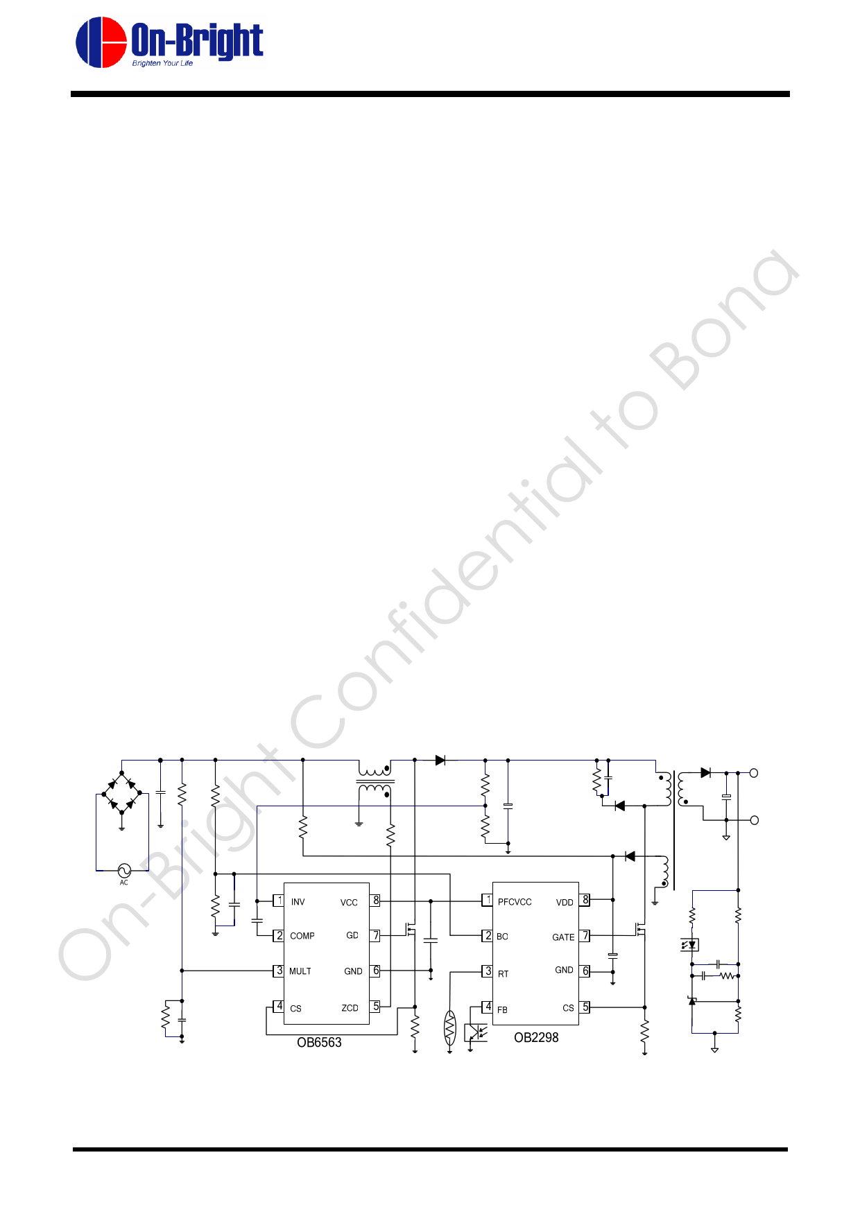
TYPICAL APPLICATION
©On-Bright Electronics
-1-
Confidential
OB_DOC_DS_9800
Free Datasheet http://www.datasheet4u.com/
1 page 
OB2298
PWM Controller with PFC Standby Control
ELECTRICAL CHARACTERISTICS
(TA = 25OC, VDD=18V, if not otherwise noted)
Symbol
Parameter
Supply Voltage (VDD) Section
Istartup
VDD start up current
I_VDD
UVLO(ON)
UVLO(OFF)
OVP(Latch)
VDD(De-Latch)
Ivdd_latch
TD_OVP
VDD_Clamp
T_Softstart
Operation current
VDD under voltage
lockout enter
VDD under voltage
lockout exit (Startup)
VDD over voltage
latch trigger
VDD latch release
threshold voltage
VDD bleeding
current at latch
shutdown
VDD OVP Debounce
time
VDD zener clamp
voltage
Soft start time
Feedback Input Section(FB Pin)
AVCS
PWM input gain
VFB_Open
FB open voltage
Test Conditions
VDD =14V, Measure
current into VDD
VFB=3V
VDD=8V
I(VDD ) = 10 mA
VFB /Vcs
IFB_Short
VTH_0D
VTH_GM
VTH_BM_on
VTH_BM_off
VTH_PL
TD_PL
ZFB_IN
VTH_PFC_off
VTH_PFC_on
FB pin short circuit
current
Zero duty cycle FB
threshold voltage
Green mode FB
threshold voltage
Burst mode on FB
threshold voltage
Burst mode off FB
threshold voltage
Power limiting FB
threshold voltage
Power limiting
debounce time
Input impedance
PFC off FB threshold
voltage
PFC on FB threshold
voltage
Current Sense Input(CS Pin) Section
T_blanking
CS input leading
edge blanking time
VTH_OC
Internal current
limiting threshold
Short FB pin to GND,
measure current
Zero duty cycle
©On-Bright Electronics
-5-
Min Typ Max Unit
5 20 uA
2.3 mA
8 9 10 V
14.5 15.5 16.5 V
26 28 30 V
6.5 V
45 uA
100
30
4
2.4
5.5
1.1
1
1.7
1.3
1.4
4.4
225
5
1.6
1.7
uSec
V
mSec
V/V
V
mA
V
V
V
V
V
mSec
Kohm
V
V
300
0.57 0.6
nSec
0.63 V
Confidential
OB_DOC_DS_9800
Free Datasheet http://www.datasheet4u.com/
5 Page 
OB2298
PWM Controller with PFC Standby Control
z Internal Synchronized Slope Compensation
Built-in slope compensation circuit adds voltage
ramp onto the current sense input voltage for PWM
generation. This greatly improves the close loop
stability at CCM and prevents the sub-harmonic
oscillation and thus reduces the output ripple
voltage.
z Over Temperature Protection (OTP)
A NTC resistor in series with a regular resistor
should connect between RT and GND for
temperature sensing and protection. NTC resistor
value becomes lower when the ambient temperature
rises. With the fixed internal current IRT flowing
through the resistors, the voltage at RT pin
becomes lower at high temperature. The internal
OTP circuit is triggered and shutdown the
MOSFET when the sensed input voltage is lower
than VTH_OTP. OTP is a latched shutdown.
z RT Pin Used as Latch Shutdown Input
Control
RT pin could also be used as a control input to
implement system latch shutdown function. An
example is to implement system OVP protection
with a latch shutdown function through a photo
coupler and affiliated circuits. When OVP detection
signal connected to RT is lower than 0.6V or higher
than 4.0V, OB2298 controls system into latch
shutdown. The recovery of the AC/DC conversion
system could be only realized by resetting internal
latch when VDD voltage drops below VDD(De-
latch) value. This could be achieved by
unplugging/re-plugging of AC source in AC start-
up configuration.
z Programmable Brownout Protection
By monitoring the level on pin BO during normal
operation, the controller protects the SMPS against
low main condition. Fig.2 illustrates brownout
protection implementation in OB2298. An internal
1.5uA current source is for brownout hysteresis
window programming. The other 0.5uA source
current is for BO pin floating protection. When BO
level falls below 1.05V, the controller and lasts for
about 100ms, the controller stops pulsing until this
level goes back and resumes operation. By
adjusting the resistor divider connected between the
high input voltage and this pin, start and stop levels
are programmable.
Figure 2
VBOP
=
( 1.05
Rlower
−
2 ×10⁻⁶ ) ×
Rupper
+ 1.05
VHYS = 1.5 ×10⁻⁶ × Rupper
z Over Load Protection (OLP)
When over load (for example, short circuit) occurs,
a fault is detected. If this fault is present for more
than 225ms, OB2298 enters an auto-recovery soft
burst mode. All pulses are stopped, VDD will drops
below UVLO(ON) and the controller will try to
restart, with the power on soft start. If the fault has
gone, the SMPS resumes operation. If the fault is
still there, the burst sequence starts again.
z Restart Timer
In some special applications, such as LCD TV, the
PWM stage is supplied by auxiliary power
converter. The typical configuration is shown in
Fig.3.
Figure 3
The front end is a PFC stage, followed by a PWM
controlled power conversion stage. The PFC stage
is controlled by PWM stage. At No/Light load,
PWM shuts down PFC for better system power
efficiency. However, the system needs a power
source to monitor the whole system operation, this
is done by a standby stage whose output provides
the power supply to PWM stage. In situations of
over loading (OLP), PWM stage enters the digital
controlled latch mode and will not be auto-
recovered since it is powered by standby stage.
OB2298 will overcome this shortcoming by an
internal restart timer. When OLP occurs, then the
timer begins counting. When counting over, the
OLP states will be cleared. If OLP still exists, then
another counting cycle begins. The counting time in
©On-Bright Electronics
- 11 -
Confidential
OB_DOC_DS_9800
Free Datasheet http://www.datasheet4u.com/
11 Page | ||
| Páginas | Total 15 Páginas | |
| PDF Descargar | [ Datasheet OB2298.PDF ] | |
Hoja de datos destacado
| Número de pieza | Descripción | Fabricantes |
| OB2298 | PWM Controller | On-Bright Electronics |
| Número de pieza | Descripción | Fabricantes |
| SLA6805M | High Voltage 3 phase Motor Driver IC. |
Sanken |
| SDC1742 | 12- and 14-Bit Hybrid Synchro / Resolver-to-Digital Converters. |
Analog Devices |
|
DataSheet.es es una pagina web que funciona como un repositorio de manuales o hoja de datos de muchos de los productos más populares, |
| DataSheet.es | 2020 | Privacy Policy | Contacto | Buscar |