|
|
|
PDF GT60N322 Data sheet ( Hoja de datos )
| Número de pieza | GT60N322 | |
| Descripción | Silicon N Channel IGBT Voltage Resonance Inverter Switching Application | |
| Fabricantes | Toshiba Semiconductor | |
| Logotipo | ||
Hay una vista previa y un enlace de descarga de GT60N322 (archivo pdf) en la parte inferior de esta página. Total 6 Páginas | ||
|
No Preview Available !
www.DataSheet4U.com
GT60N322
TOSHIBA Insulated Gate Bipolar Transistor Silicon N Channel IGBT
GT60N322
Voltage Resonance Inverter Switching Application
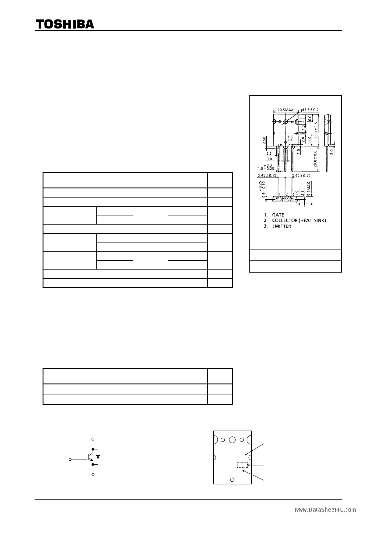
Unit: mm
• Enhancement mode type
• High speed
: tf = 0.11 μs (typ.) (IC = 60 A)
• Low saturation voltage : VCE (sat) = 2.4 V (typ.) (IC = 60 A)
• FRD included between emitter and collector
• TO-3P(LH) (Toshiba package name)
Absolute Maximum Ratings (Ta = 25°C)
Characteristics
Symbol
Rating
Unit
Collector-emitter voltage
Gate-emitter voltage
Continuous collector @ Tc = 100°C
current
@ Tc = 25°C
Pulsed collector current
DC
Diode forward current
Pulsed
Collector power
dissipation
@ Tc = 100°C
@ Tc = 25°C
Junction temperature
Storage temperature range
VCES
VGES
IC
ICP
IF
IFP
PC
Tj
Tstg
1000
±25
29
57
120
15
120
80
200
150
−55 to 150
V
V
A
A
A
W
°C
°C
JEDEC
―
JEITA
―
TOSHIBA
2-21F2C
Weight: 9.75 g (typ.)
Note: Using continuously under heavy loads (e.g. the application of high temperature/current/voltage and the
significant change in temperature, etc.) may cause this product to decrease in the reliability significantly even
if the operating conditions (i.e. operating temperature/current/voltage, etc.) are within the absolute maximum
ratings.
Please design the appropriate reliability upon reviewing the Toshiba Semiconductor Reliability Handbook
(“Handling Precautions”/Derating Concept and Methods) and individual reliability data (i.e. reliability test report
and estimated failure rate, etc).
Thermal Characteristics
Characteristics
Thermal resistance (IGBT)
Thermal resistance (diode)
Symbol
Rth (j-c)
Rth (j-c)
Max
0.625
4.0
Unit
°C/W
°C/W
Equivalent Circuit
Marking
Gate
Collector
Emitter
TOSHIBA
GT60N322
JAPAN
Part No. (or abbreviation code)
Lot No.
A line indicates
lead (Pb)-free package or
lead (Pb)-free finish.
1 2006-11-01
1 page 
www.DataSheet4U.com
GT60N322
Tc = 25°C
101
100
10−1
Rth (t) – tw
Diode stage
IGBT stage
10−2
10−5
10−4
10−3
10−2
10−1
100
101
102
Pulse width tw (s)
IC max – Tc
60
Common emitter
VGE = 15 V
50
40
30
20
10
0
25 50 75 100 125 150
Case temperature Tc (°C)
100
Common
collector
80
IF – VF
60
40
20
Tc = 125 °C
−40
25
0
0.0 0.5 1.0 1.5 2.0
Forward voltage VF (V)
2.5
1.0
Common Collector
di/dt = −20 A/µs
Tc = 25°C
0.8
trr, lrr – IF
0.6
trr
0.4
lrr
0.2
0.0
0 20 40 60
Forward current IF (A)
10
9
8
7
6
5
80
trr, lrr – di/dt
1.0
Common collector
IF = 60 A
Tc = 25°C
0.8
trr
0.6
50
40
30
0.4
lrr
0.2
20
10
0.0 0
0 40 80 120 160 200
di/dt (A/µs)
5 2006-11-01
5 Page | ||
| Páginas | Total 6 Páginas | |
| PDF Descargar | [ Datasheet GT60N322.PDF ] | |
Hoja de datos destacado
| Número de pieza | Descripción | Fabricantes |
| GT60N321 | High Power Switching Applications The 4th Generation | Toshiba Semiconductor |
| GT60N322 | Silicon N Channel IGBT Voltage Resonance Inverter Switching Application | Toshiba Semiconductor |
| Número de pieza | Descripción | Fabricantes |
| SLA6805M | High Voltage 3 phase Motor Driver IC. |
Sanken |
| SDC1742 | 12- and 14-Bit Hybrid Synchro / Resolver-to-Digital Converters. |
Analog Devices |
|
DataSheet.es es una pagina web que funciona como un repositorio de manuales o hoja de datos de muchos de los productos más populares, |
| DataSheet.es | 2020 | Privacy Policy | Contacto | Buscar |