|
|
|
PDF STA120 Data sheet ( Hoja de datos )
| Número de pieza | STA120 | |
| Descripción | DIGITAL AUDIO INTERFACE RECEIVER | |
| Fabricantes | STMicroelectronics | |
| Logotipo | ||
Hay una vista previa y un enlace de descarga de STA120 (archivo pdf) en la parte inferior de esta página. Total 15 Páginas | ||
|
No Preview Available !
www.DataSheet4U.com
STA120
DIGITAL AUDIO INTERFACE RECEIVER
s MONOLITHIC CMOS RECEIVER
s 3.3V SUPPLY VOLTAGE
s LOW-JITTER, ON-CHIP CLOCK RECOVERY
256xFs OUTPUT CLOCK PROVIDED
s SUPPORTS: AES/EBU, IEC 958, S/PDIF, &
EIAJ CP-340/1201 PROFESSIONAL AND
CONSUMER FORMATS
s EXTENSIVE ERROR REPORTING REPEAT
LAST SAMPLE ON ERROR OPTION
DESCRIPTION
The STA120 is a monolithic CMOS device that re-
ceives and decodes audio data according to the
AES/EBU, IEC 958, S/PDIF, & EIAJ CP-340/1201
interface standards.
The STA120 recovers the clock and synchroniza-
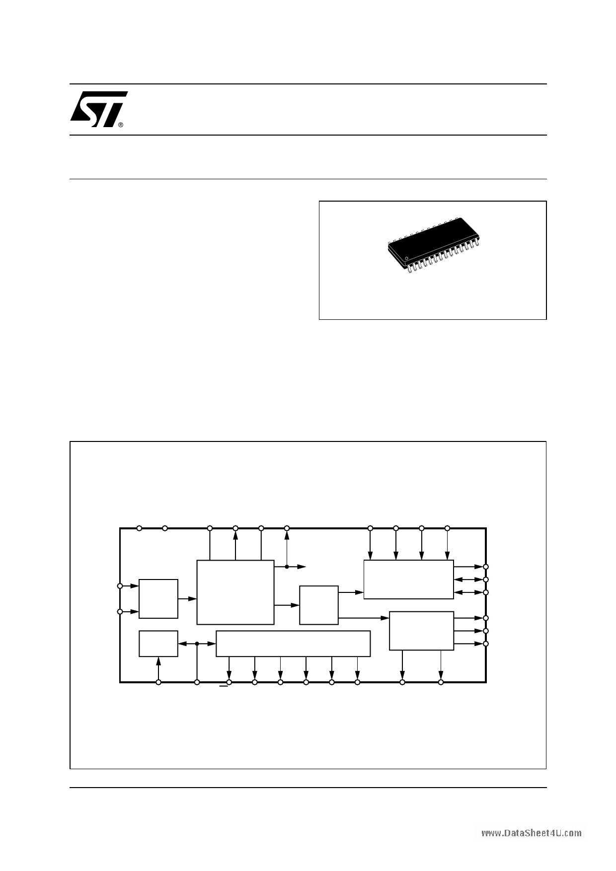
BLOCK DIAGRAM
SO28
ORDERING NUMBER: STA120D
tion signals and de-multiplexes the audio and dig-
ital data. Differential or single ended inputs can be
decoded.
The STA120 de-multiplexes the channel, user and
validity data directly to serial output pins with ded-
icated output pins for the most important channel
status bits.
VD+ DGND
78
VA+ FILT AGND MCK
22 20 21 19
RXP
RXN
9
RS422
10 Receiver
MUX
CLOCK & DATA
RECOVERY
DE MUX
MUX
M3 M2 M1 M0
17 18 24 23
AUDIO
SERIAL PORT
REGISTERS
26
SDATA
12
SCK
11
FSYNC
1
C
14
U
28
VREF
13
CS12/FCK
16 6 5 4 3 2 27
SEL C0/E0 Ca/E1 Cb/E2 Cc/F0 Cd/F1 Ce/F2
25
ERF
15
CBL D97AU613A
December 2002
1/15
1 page 
www.DataSheet4U.com
STA120
Figure 1. Circuit Diagram
3.3V
ANALOG
3.3V
DIGITAL
RECEIVER
CIRCUIT
(See Appendix A)
0.1µF
AGND
RXP
RXN
CS12/FCK
CHANNEL STATUS
and/or
ERROR/FREQUENCY
REPORTING
SEL
ERF
C/E-F bits
FILT
330Ω
0.47µF
15nF
0.1µF
VA+ VD+
22
21
7
MCK
19
9 VERF
28
SCK
10 12
SDATA
26
13
STA120
FSYNC
11
16
25
C
1
6U
14
CBL
20 15
8
DGND
AUDIO
DATA
PROCESSOR
µCONTROLLER
or
LOGIC
D97AU611
GENERAL DESCRIPTION
The STA120 is a monolithic CMOS circuit that receives and decodes audio and digital data according to
the AES/EBU, IEC 958, S/PDIF, and EIAJ CP-340/1201 interface standards.
It contains a RS422 line receiver and Phase-Locked Loops (PLL) that recovers the clock and synchroni-
zation signals and de-multiplexes the audio and digital data. The STA120 de-multiplexes the channel sta-
tus, user and validity information directly to serial output pins with dedicated pins for the most important
channel status bits.
Line Receiver
The line receiver can decode differential as well as single ended inputs. The receiver consits of a differ-
ential input Schmitt trigger with 50mV of hysteresis. The hysteresis prevents noisy signals from corrupting
the phase detector. Appendix A contains more information on how to configure the line receivers for dif-
ferential and single ended signals.
Clocks and Jitter Attenuation
The primary function of this chip is to recover audio data and low jitter clocks from a digital audio trans-
mission line. The clocks that can be generated are MCK (256xFS), SCK (64xFS), and FSYNC (FS or
2xFS). MCK is the output of the voltage controlled oscillator which is a component of the PLL. The PLL
consists of phase and frequency detectors, a second-order loop filter, and a voltage controlled oscillator.
All components of the PLL are on chip with the exception of a resistor and capacitors used in the loop filter.
This filter is connected between the FILT pin and AGND. The closed-loop transfer function, which speci-
fies the PLL's jitter attenuation characteristics, is shown in Figure 2.
The loop will begin to attenuate jitter at approximately 25kHz with another pole at 80kHz and will have
50dB of attenuation by 1MHz. Since most data jitter introduced by the transmission line is high in frequen-
cy, it will be strongly attenuated.
Multiple frequency detectors are used to minimize the time it takes the PLL to lock to the incoming data
stream and to prevent false lock conditions. When the PLL is not locked to the incoming data stream, the
5/15
5 Page 
www.DataSheet4U.com
STA120
Professional Channel Status (C0 = 0)
When C0 is low, the received channel status block is encoded according to the professional / broadcast
format. The Ca through Ce pins are defined for some of the more important professional bits. As listed in
Table 5, Ca is the inverse of channel status bit1. Therefore, if the incoming channel status bit1. Therefore,
if the incoming channel status bit 1 is 1, Ca, defined as C1, will be 0. C1 indicates whether audio (C1 = 1)
or non-audio (C1 = 0) data is being received. Cb and Cc, defined as EM0 and EM1 respectively, indicate
emphasis and are encoded version of channel status bits 2, 3, and 4. The decoding is listed in Table 6.
Cd, defined as C9, is the inverse of channel status bit 9, which gives some indication of channel status bit
9, which gives some indication of channel mode. (Bit 9 is also defined as bit 1 of byte 1). When Ce, defined
as CRCE, is low, the STA120 calculated CRC value does not match the received CRC value. This signal
may be used to qualify Ca through Cd. If Ca through Ce are being displayed, Ce going low can indicate
not to update the display.
Table 6. Emphasis Encoding
EM1
0
0
1
1
EM0
0
1
0
1
C2
1
1
1
0
C3
1
1
0
0
C4 Emphasis
1 CCITT J.17 emphasis
0 50/15ms emphasis
0 No emphasis
0 Not indicated
Consumer Channel Status (C0 = 1)
When C0 is high, the received channel status block is encoded according to the consumer format. In this
case Ca through Ce are defined differently as shown in Table 5.
Ca is the inverse of channel status bit 1, C1, indicating audio (C1 = 1) or non-audio (C1 = 0). Cb is defined
as the inverse of channel status bit 2, C2, which indicates copy inhibit/copyright information Cc, defined
as C3, is the emphasis bit of channel status, with C3 low indicating the data has had pre-emphasis added.
The audio standards, in consumer mode, describe bit 15, L, as the generation status which indicates
whether the audio data is an original work or a copy (1st generation or higher). The definition of the Lbit is
reversed for three category codes: two broadcast codes, and laser-optical (CD's). Therefore, to interpret
the L bit properly, the category code must be decoded. The STA120 does this decoding internally and pro-
vides the ORIG signal that, when low, indicates that the audio data is original over all category codes.
SCMS
The consumer audio standards also mention a serial copy management system, SCMS, for dealing with
copy protection of copyrighted works. SCMS is designed to allow unlimited duplication of the original work,
but no duplication of any copies of the original. This system utilizes the channel status bit 2, Copy, and
channel status bit 15, L or generation status, along with the category codes. If the Copy bit is 0, copyright
protection is asserted over the material is an original or a duplication. (As mentioned in the previous para-
graph, the definition of the L bit can be reversed based on the category codes.) There are two category
codes that get special attention: general and A/D converters without C or L bit information. For these two
categories the SCMS standard requires that equipment interfacing to these categories set the C bit to 0
(copyright protection asserted) and the L bit to 1 (original). To support this feature, Ce, in the consumer
mode, is defined as IGCAT (ignorant category) which is low for the "general" (0000000) and "A/D convert-
er without copyright information" (01100xx) categories.
11/15
11 Page | ||
| Páginas | Total 15 Páginas | |
| PDF Descargar | [ Datasheet STA120.PDF ] | |
Hoja de datos destacado
| Número de pieza | Descripción | Fabricantes |
| STA120 | DIGITAL AUDIO INTERFACE RECEIVER | STMicroelectronics |
| STA124 | PNP Silicon Transistor | AUK |
| STA124M | PNP Silicon Transistor | AUK |
| STA124N | PNP Silicon Transistor | AUK |
| Número de pieza | Descripción | Fabricantes |
| SLA6805M | High Voltage 3 phase Motor Driver IC. |
Sanken |
| SDC1742 | 12- and 14-Bit Hybrid Synchro / Resolver-to-Digital Converters. |
Analog Devices |
|
DataSheet.es es una pagina web que funciona como un repositorio de manuales o hoja de datos de muchos de los productos más populares, |
| DataSheet.es | 2020 | Privacy Policy | Contacto | Buscar |