|
|
|
PDF ISL2110 Data sheet ( Hoja de datos )
| Número de pieza | ISL2110 | |
| Descripción | (ISL2110 / ISL2111) High Frequency Half-Bridge Drivers | |
| Fabricantes | Intersil Corporation | |
| Logotipo | ||
Hay una vista previa y un enlace de descarga de ISL2110 (archivo pdf) en la parte inferior de esta página. Total 11 Páginas | ||
|
No Preview Available !
®
Data Sheet
ISL2110, ISL2111
July 11, 2006
FN6295.1
100V, 3A/4A Peak, High Frequency
Half-Bridge Drivers
The ISL2110, ISL2111 are 100V, high frequency, half-bridge
N-channel power MOSFET driver ICs. They are based on
the popular HIP2100, HIP2101 half-bridge drivers, but offer
several performance improvements. Peak output pull-up/
pull-down current has been increased to 3A/4A, which
significantly reduces switching power losses and eliminates
the need for external totem-pole buffers in many
applications. Also, the low end of the VDD operational supply
range has been extended to 8VDC. The ISL2110 has
additional input hysteresis for superior operation in noisy
environments and the inputs of the ISL2111, like those of the
ISL2110, can now safely swing to the VDD supply rail.
Ordering Information
PART
NUMBER
PART
TEMP.
(Notes 1, 2) MARKING RANGE (°C)
PACKAGE
(Pb-Free)
PKG.
DWG. #
ISL2110ABZ 2110ABZ -40 to 125 8 Ld SOIC
M8.15
ISL2110AR4Z 2110AR4Z -40 to 125 12 Ld 4x4 DFN L12.4x4A
ISL2111ABZ 2111ABZ
www.DataSheet4U.com
ISL2111AR4Z 2111AR4Z
-40 to 125 8 Ld SOIC
M8.15
-40 to 125 12 Ld 4x4 DFN L12.4x4A
NOTES:
1. Intersil Pb-free plus anneal products employ special Pb-free
material sets; molding compounds/die attach materials and 100%
matte tin plate termination finish, which are RoHS compliant and
compatible with both SnPb and Pb-free soldering operations.
Intersil Pb-free products are MSL classified at Pb-free peak
reflow temperatures that meet or exceed the Pb-free
requirements of IPC/JEDEC J STD-020.
2. Add “-T” suffix for Tape and Reel packing option.
Features
• Drives N-Channel MOSFET Half-Bridge
• SOIC and DFN Package Options
• SOIC and DFN Packages Compliant with 100V Conductor
Spacing Guidelines per IPC-2221
• Pb-Free Plus Anneal Available (RoHS Compliant)
• Bootstrap Supply Max Voltage to 114VDC
• On-Chip 1Ω Bootstrap Diode
• Fast Propagation Times for Multi-MHz Circuits
• Drives 1nF Load with Typical Rise/Fall Times of 9ns/7.5ns
• CMOS Compatible Input Thresholds (ISL2110)
• 3.3V/TTL Compatible Input Thresholds (ISL2111)
• Independent Inputs Provide Flexibility
• No Start-Up Problems
• Outputs Unaffected by Supply Glitches, HS Ringing Below
Ground or HS Slewing at High dv/dt
• Low Power Consumption
• Wide Supply Voltage Range (8V to 14V)
• Supply Undervoltage Protection
• 1.6Ω/1Ω Typical Output Pull-Up/Pull-Down Resistance
Applications
• Telecom Half-Bridge DC/DC Converters
• Telecom Full-Bridge DC/DC Converters
• Two-Switch Forward Converters
• Active-Clamp Forward Converters
• Class-D Audio Amplifiers
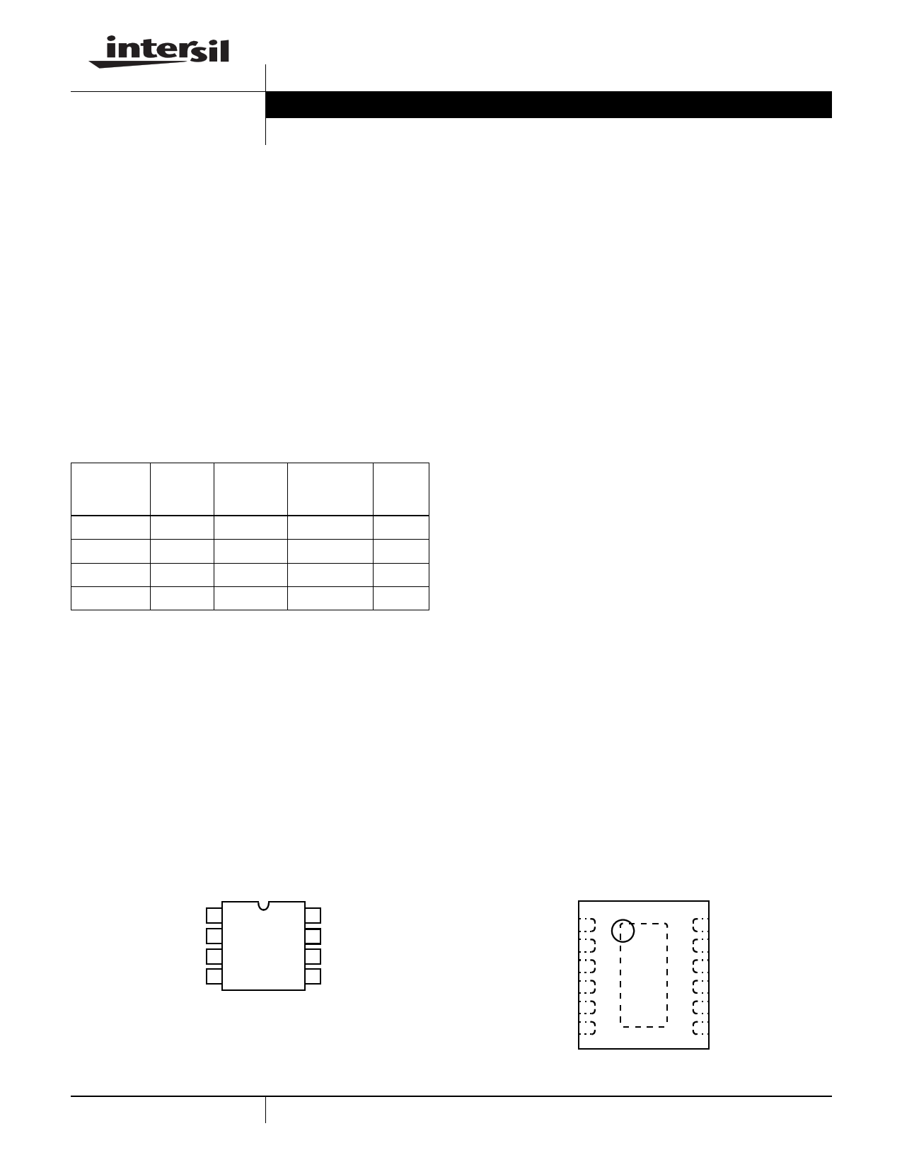
Pinouts
ISL2110, ISL2111 (SOIC)
TOP VIEW
VDD 1
HB 2
HO 3
HS 4
8 LO
7 VSS
6 LI
5 HI
NOTE: EPAD = Exposed PAD.
1
ISL2110, ISL2111 (DFN)
TOP VIEW
VDD 1
NC 2
NC 3
HB 4
HO 5
HS 6
EPAD
12 LO
11 VSS
10 NC
9 NC
8 LI
7 HI
CAUTION: These devices are sensitive to electrostatic discharge; follow proper IC Handling Procedures.
1-888-INTERSIL or 1-888-468-3774 | Intersil (and design) is a registered trademark of Intersil Americas Inc.
Copyright © Intersil Americas Inc. 2006. All Rights Reserved.
All other trademarks mentioned are the property of their respective owners.
1 page 
ISL2110, ISL2111
Electrical Specifications
PARAMETERS
VDD = VHB = 12V, VSS = VHS = 0V, No Load on LO or HO, Unless Otherwise Specified (Continued)
TJ = 25°C
TJ = -40°C to
125°C
SYMBOL
TEST CONDITIONS
MIN TYP MAX MIN MAX UNITS
HB Rising Threshold
HB Threshold Hysteresis
BOOT STRAP DIODE
VHBR
VHBH
5.5 6.1 6.8 5.0 7.1
- 0.6 - - -
V
V
Low Current Forward Voltage
High Current Forward Voltage
Dynamic Resistance
LO GATE DRIVER
VDL
VDH
RD
IVDD-HB = 100µA
IVDD-HB = 100mA
IVDD-HB = 100mA
- 0.5 0.6 - 0.7 V
- 0.7 0.9 - 1 V
- 0.7 1
- 1.5 Ω
Low Level Output Voltage
High Level Output Voltage
Peak Pull-Up Current
Peak Pull-Down Current
HO GATE DRIVER
VOLL
VOHL
IOHL
IOLL
ILO = 100mA
ILO = -100mA, VOHL = VDD - VLO
VLO = 0V
VLO = 12V
- 0.1 0.18 - 0.25 V
- 0.16 0.23 - 0.3 V
-3- - - A
-4- - - A
Low Level Output Voltage
High Level Output Voltage
Peak Pull-Up Current
Peak Pull-Down Current
VOLH
VOHH
IOHH
IOLH
IHO = 100mA
IHO = -100mA, VOHH = VHB - VHO
VHO = 0V
VHO = 12V
- 0.1 0.18 - 0.25 V
- 0.16 0.23 - 0.3 V
-3- - - A
-4- - - A
Switching Specifications VDD = VHB = 12V, VSS = VHS = 0V, No Load on LO or HO, Unless Otherwise Specified
PARAMETERS
SYMBOL
TEST
CONDITIONS
TJ = 25°C
MIN TYP MAX
TJ = -40°C
to 125°C
MIN MAX UNITS
Lower Turn-Off Propagation Delay (LI Falling to LO Falling)
Upper Turn-Off Propagation Delay (HI Falling to HO Falling)
Lower Turn-On Propagation Delay (LI Rising to LO Rising)
Upper Turn-On Propagation Delay (HI Rising to HO Rising)
Delay Matching: Upper Turn-Off to Lower Turn-On
Delay Matching: Lower Turn-Off to Upper Turn-On
Either Output Rise Time (10% to 90%)
Either Output Fall Time (90% to 10%)
Either Output Rise Time (3V to 9V)
Either Output Fall Time (9V to 3V)
Minimum Input Pulse Width that Changes the Output
Bootstrap Diode Turn-On or Turn-Off Time
tLPHL
tHPHL
tLPLH
tHPLH
tMON
tMOFF
tRC
tFC
tR
tF
tPW
tBS
CL = 1nF
CL = 1nF
CL = 0.1µF
CL = 0.1µF
- 32 50 - 60 ns
- 32 50 - 60 ns
- 39 50 - 60 ns
- 38 50 - 60 ns
1 8 - - 16 ns
1 6 - - 16 ns
- 9 - - - ns
- 7.5 - - - ns
- 0.3 0.4 - 0.5 µs
- 0.19 0.3 - 0.4 µs
- - - - 50 ns
- 10 - - - ns
5 FN6295.1
July 11, 2006
5 Page 
ISL2110, ISL2111
Small Outline Plastic Packages (SOIC)
N
INDEX
AREA
E
-B-
H
0.25(0.010) M B M
123
-A-
D
SEATING PLANE
A
L
h x 45°
-C-
e A1
B
0.25(0.010) M C A M B S
α
0.10(0.004)
C
NOTES:
1. Symbols are defined in the “MO Series Symbol List” in Section 2.2 of
Publication Number 95.
2. Dimensioning and tolerancing per ANSI Y14.5M-1982.
3. Dimension “D” does not include mold flash, protrusions or gate burrs.
Mold flash, protrusion and gate burrs shall not exceed 0.15mm (0.006
inch) per side.
4. Dimension “E” does not include interlead flash or protrusions. Inter-
lead flash and protrusions shall not exceed 0.25mm (0.010 inch) per
side.
5. The chamfer on the body is optional. If it is not present, a visual index
feature must be located within the crosshatched area.
6. “L” is the length of terminal for soldering to a substrate.
7. “N” is the number of terminal positions.
8. Terminal numbers are shown for reference only.
9. The lead width “B”, as measured 0.36mm (0.014 inch) or greater
above the seating plane, shall not exceed a maximum value of
0.61mm (0.024 inch).
10. Controlling dimension: MILLIMETER. Converted inch dimensions
are not necessarily exact.
M8.15 (JEDEC MS-012-AA ISSUE C)
8 LEAD NARROW BODY SMALL OUTLINE PLASTIC PACKAGE
INCHES
MILLIMETERS
SYMBOL MIN MAX MIN MAX NOTES
A
0.0532 0.0688 1.35
1.75
-
A1
0.0040 0.0098 0.10
0.25
-
B
0.013 0.020 0.33
0.51
9
C
0.0075 0.0098 0.19
0.25
-
D
0.1890 0.1968 4.80
5.00
3
E
0.1497 0.1574 3.80
4.00
4
e 0.050 BSC
1.27 BSC
-
H
0.2284 0.2440 5.80
6.20
-
h
0.0099 0.0196 0.25
0.50
5
L
0.016 0.050 0.40
1.27
6
N8
87
α 0° 8° 0° 8° -
Rev. 1 6/05
All Intersil U.S. products are manufactured, assembled and tested utilizing ISO9000 quality systems.
Intersil Corporation’s quality certifications can be viewed at www.intersil.com/design/quality
Intersil products are sold by description only. Intersil Corporation reserves the right to make changes in circuit design, software and/or specifications at any time without
notice. Accordingly, the reader is cautioned to verify that data sheets are current before placing orders. Information furnished by Intersil is believed to be accurate and
reliable. However, no responsibility is assumed by Intersil or its subsidiaries for its use; nor for any infringements of patents or other rights of third parties which may result
from its use. No license is granted by implication or otherwise under any patent or patent rights of Intersil or its subsidiaries.
For information regarding Intersil Corporation and its products, see www.intersil.com
11 FN6295.1
July 11, 2006
11 Page | ||
| Páginas | Total 11 Páginas | |
| PDF Descargar | [ Datasheet ISL2110.PDF ] | |
Hoja de datos destacado
| Número de pieza | Descripción | Fabricantes |
| ISL2110 | (ISL2110 / ISL2111) High Frequency Half-Bridge Drivers | Intersil Corporation |
| ISL2111 | (ISL2110 / ISL2111) High Frequency Half-Bridge Drivers | Intersil Corporation |
| Número de pieza | Descripción | Fabricantes |
| SLA6805M | High Voltage 3 phase Motor Driver IC. |
Sanken |
| SDC1742 | 12- and 14-Bit Hybrid Synchro / Resolver-to-Digital Converters. |
Analog Devices |
|
DataSheet.es es una pagina web que funciona como un repositorio de manuales o hoja de datos de muchos de los productos más populares, |
| DataSheet.es | 2020 | Privacy Policy | Contacto | Buscar |