|
|
|
PDF ST20-GP6 Data sheet ( Hoja de datos )
| Número de pieza | ST20-GP6 | |
| Descripción | GPS PROCESSOR | |
| Fabricantes | ST Microelectronics | |
| Logotipo | ||
Hay una vista previa y un enlace de descarga de ST20-GP6 (archivo pdf) en la parte inferior de esta página. Total 30 Páginas | ||
|
No Preview Available !
® ST20-GP6
GPS PROCESSOR
FEATURES
s Application specific features
• 12 channel GPS correlation DSP hardware,
ST20 CPU (for control and position
calculations) and memory on one chip
• no TCXO required
• RTCA-SC159 / WAAS / EGNOS supported
s GPS performance
• accuracy
- stand alone with SA on <100m, SA off <30m
- differential <1m
- surveying <1cm
• time to first fix
- autonomous start 90s
- cold start 45s
- warm start 7s
- obscuration 1s
s Enhanced 32-bit VL-RISC CPU - C2 core
• 16/33/50 MHz processor clock
• 25 MIPS at 33 MHz
• fast integer/bit operations
s 64 Kbytes on-chip SRAM
s 128 Kbytes on-chip ROM
s Programmable memory interface
• 4 separately configurable regions
• 8/16-bits wide
• support for mixed memory
• 2 cycle external access
s Programmable UART (ASC)
s Parallel I/O
s Vectored interrupt subsystem
s Diagnostic control unit
s Power management
• low power operation
• power down modes
s Professional toolset support
• ANSI C compiler/link driver and libraries
• Debugging/profiling and simulation tools
s Technology
• Static clocked 50 MHz design
• 3.3 V, sub micron technology
s 100 pin PQFP package
s JTAG Test Access Port
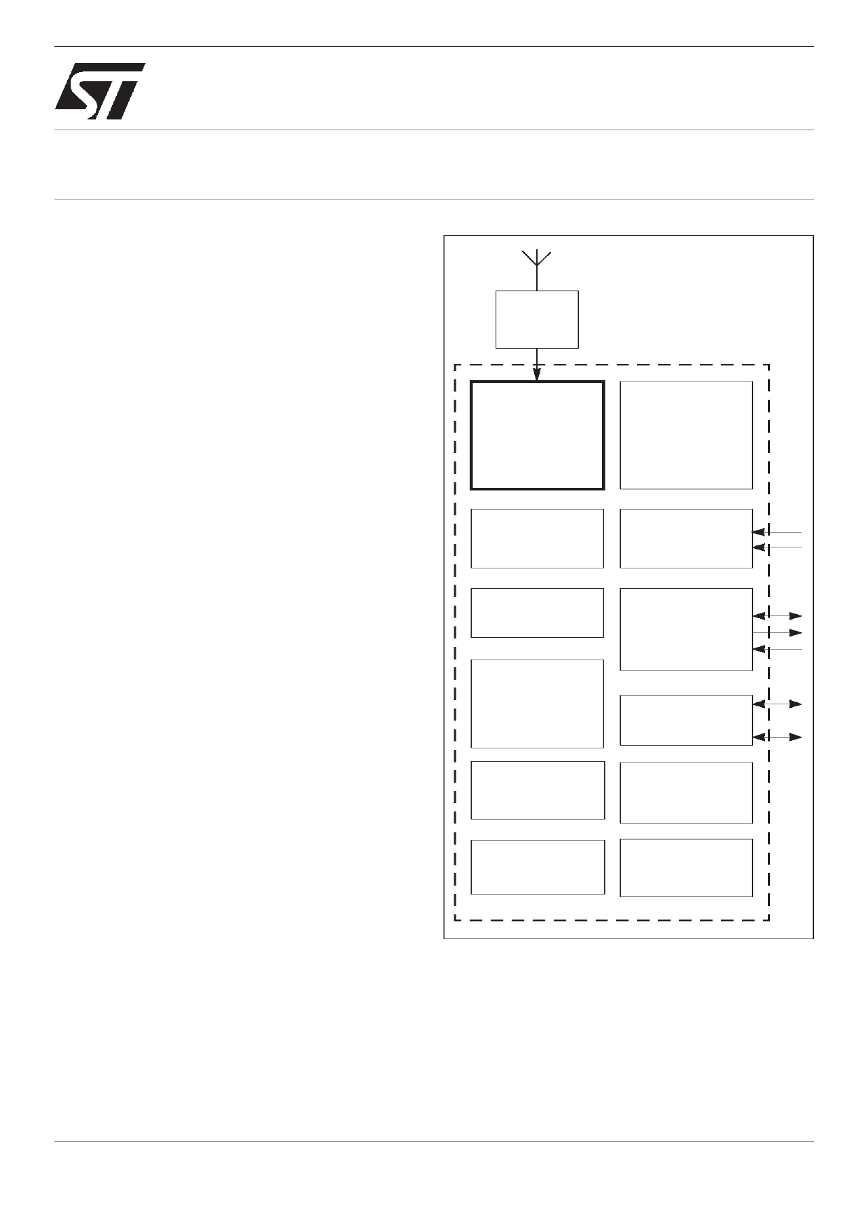
PRELIMINARY DATA
GPS
radio
12 channel GPS
hardware DSP
ST20-GP6
ST20
CPU
Low
power
controller
Interrupt
controller
Real time
clock/calendar
Programmable
memory
interface
Serial
communications
2 UART (ASC)
Parallel
input/output
... 16
64K
SRAM
Diagnostic
control unit
128K optional
mask ROM
Test
access port
APPLICATIONS
s Global Positioning System (GPS) receivers
s Car navigation systems
s Fleet management systems
s Time reference for telecom systems
December 1998
The information in this datasheet is subject to change
42 1707 02
1/123
1 page 
ST20-GP6
1 Introduction
The ST20-GP6 is an application-specific single chip micro using the ST20 CPU with
microprocessor style peripherals added on-chip. It incorporates DSP hardware for processing the
signals from GPS (Global Positioning System) satellites.
The twelve channel GPS correlation DSP hardware is designed to handle twelve satellites, two of
which can be initialized to support the RTCA-SC159 specifi cation for WAAS (Wide Area
Augmentation Service) and EGNOS (European Geostationary Navigation Overlay System)
services.
The ST20-GP6 has been designed to minimize system costs and reduce the complexity of GPS
systems. It offers all hardware DSP and microprocessor functions on one chip and provides
suffi cient on-chip RAM and ROM. The entire analogue section, RF and clock generation are
available on a companion chip. Thus, a complete GPS system is possible using just two chips, see
Figure 1.1.
Antenna
ST20-GP6
STB5600
Radio
Single chip
DSP
ASIC
Low
cost
crystal
No TCXO
CPU
Watchdog
timer
UART
Parallel
I/O
Real
time
clock
optional
mask ROM
RAM
Driver
(optional)
Parallel I/O
Figure 1.1 GPS system
The ST20-GP6 supports large values of frequency offset, allowing the use of a very low cost
oscillator, thus saving the cost of a Temperature Controlled Crystal Oscillator (TCXO).
The CPU and software have access to the part-processed signal to enable accelerated acquisition
time.
5/123
5 Page 
ST20-GP6
3 Digital signal processing module
The ST20-GP6 chip includes 12 channel GPS correlation DSP hardware. It is designed to handle
twelve satellites, two of which can be initialized to support the RTCA-SC159 specifi cation.
The digital signal processing (DSP) module extracts GPS data from the incoming IF (Intermediate
Frequency) data. There are a number of stages of processing involved; these are summarized
below and in Figure 3.1. After the 12 pairs of hardware correlators, the data for all channels are
time division multiplexed onto the appropriate internal buses (i.e. values for each channel are
passed in sequence, for example: I1, Q1, I2, Q2 ... I12, Q12, I1, Q1).
4 MHz IF
input
frequency
converter A
data
sampler
I correlator
(x 12)
Q correlator
(x 12)
frequency
converter B
DMA
interface
accumulator
Pseudo random
noise sequence
generator
(x 12)
Numerically
controlled
oscillator
ST20 CPU accessible
registers
Figure 3.1 DSP module block diagram
The main stages of processing are as follows:
Data sampling
This stage removes any meta-stability caused by the asynchronous input data coming from an
analogue source (the radio receiver). The data at this point consists of a carrier of nominally
4.092 MHz with a bandwidth of approximately ±1 MHz.
This stage is common to all 12 channels.
11/123
11 Page | ||
| Páginas | Total 30 Páginas | |
| PDF Descargar | [ Datasheet ST20-GP6.PDF ] | |
Hoja de datos destacado
| Número de pieza | Descripción | Fabricantes |
| ST20-GP1 | GPS PROCESSOR | ST Microelectronics |
| ST20-GP6 | GPS PROCESSOR | ST Microelectronics |
| Número de pieza | Descripción | Fabricantes |
| SLA6805M | High Voltage 3 phase Motor Driver IC. |
Sanken |
| SDC1742 | 12- and 14-Bit Hybrid Synchro / Resolver-to-Digital Converters. |
Analog Devices |
|
DataSheet.es es una pagina web que funciona como un repositorio de manuales o hoja de datos de muchos de los productos más populares, |
| DataSheet.es | 2020 | Privacy Policy | Contacto | Buscar |