|
|
|
PDF V23826-K305-C53 Data sheet ( Hoja de datos )
| Número de pieza | V23826-K305-C53 | |
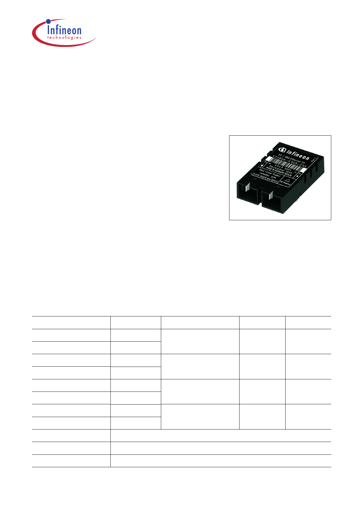
| Descripción | Multimode 850 nm 1.0625 Gbit/s Fibre Channel 1.3 Gigabit Ethernet 1x9 Transceiver | |
| Fabricantes | Infineon Technologies | |
| Logotipo | ||
Hay una vista previa y un enlace de descarga de V23826-K305-C53 (archivo pdf) en la parte inferior de esta página. Total 17 Páginas | ||
|
No Preview Available !
Multimode 850 nm
1.0625 Gbit/s Fibre Channel
1.3 Gigabit Ethernet 1x9 Transceiver
Fiber Optics
V23826-K305-Cxx/Cxxx
Features
• Compliant with Fibre Channel and
Gigabit Ethernet standard
• Meets mezzanine standard height of 9.8 mm
• Compact integrated transceiver unit with
– VCSEL transmitter
– Integrated receiver
– Duplex SC receptacle
• Class 1 FDA and IEC laser safety compliant
• FDA Accession No. 9520890-18
• Single power supply (5 V or 3.3 V)
• Signal detect indicator (PECL and TTL version)
• PECL differential inputs and outputs
• Process plug included
• Performance exceeds FC 100-M5-SLI
• Wave solderable and washable with process plug inserted
• For distances of up to 550 m on multimode fiber
Part Number
Voltage
Signal Detect
Input
V23826-K305-C13 5 V
PECL
AC
V23826-K305-C313 3.3 V
V23826-K305-C53 5 V
TTL
AC
V23826-K305-C353
V23826-K305-C631)
V23826-K305-C3631)
3.3 V
5V
3.3 V
PECL
DC
V23826-K305-C73 5 V
PECL
AC
V23826-K305-C373 3.3 V
Add Suffix to PIN Shield Options
-C3 Metallized cover, forward springs
-D3 Metallized cover, backward springs
1) Standard version
Data Sheet
1
File: 1159
Output
DC
AC
DC
AC
2004-01-27
1 page 
V23826-K305-Cxx/Cxxx
Description
The transmitter contains a laser driver circuit that drives the modulation and bias current
of the laser diode. The currents are controlled by a power control circuit to guarantee
constant output power of the laser over temperature and aging.
The power control uses the output of the monitor PIN diode (mechanically built into the
laser coupling unit) as a controlling signal, to prevent the laser power from exceeding the
operating limits.
Single fault condition is ensured by means of an integrated automatic shutdown circuit
that disables the laser when it detects transmitter failures. A reset is only possible by
turning the power off, and then on again.
The transceiver contains a supervisory circuit to control the power supply. This circuit
generates an internal reset signal whenever the supply voltage drops below the reset
threshold. It keeps the reset signal active for at least 140 milliseconds after the voltage
has risen above the reset threshold. During this time the laser is inactive.
Regulatory Compliance
Feature
Standard
Comments
ESD:
MIL-STD 883D
Electrostatic Discharge to the Method 3015.7
Electrical Pins
JESD22-A114-B
Class 1 (> 1000 V) HBM
Class 1C
Immunity:
EN 61000-4-2
Electrostatic Discharge (ESD) IEC 61000-4-2
to the Duplex SC Receptacle
Discharges of ±15 kV with an air
discharge probe on the receptacle
cause no damage.
Immunity:
Radio Frequency
Electromagnetic Field
EN 61000-4-3
IEC 61000-4-3
With a field strength of 3 V/m,
noise frequency ranges from
10 MHz to 1 GHz. No effect on
transceiver performance between
the specification limits.
Emission:
Electromagnetic Interference
(EMI)
FCC 47 CFR Part
15 Class B
EN 55022 Class B
CISPR 22
Noise frequency range:
30 MHz to 18 GHz;
Margins depend on PCB layout
and chassis design.
Data Sheet 5 2004-01-27
5 Page 
V23826-K305-Cxx/Cxxx
Application Notes
Multimode 850 nm Gigabit Ethernet/Fibre Channel 1x9 Transceiver,
DC/DC Version
Laser
Driver
VEETx 9
TD+ 8
1)
TD− 7
C6
C7
VCC SerDes
5 V / 3.3 V
Infineon Transceiver
Signal
Detect
Pre-
Amp
Limiting RD+
Amplifier
RD−
VCCTx 6
VCCRx 5
C1
SD 4
C2
1)
RD+ 3
RD− 2
L1 VCC
5 V / 3.3 V
L2
C3
SD to upper level
R9
C4
C5
VEERx 1
VCC
Tx+
ECL/PECL
Driver
Tx-
Serializer/
Deserializer
RD-
RD+
Receiver
PLL etc.
C1/2/3 = 4.7 µF
C4/5/6/7 = 100 nF
L1/2 = 1 µH
R5/6 = 270 Ω (5 V)
= 150 Ω (3.3 V)
R7/8 = 127 Ω (5 V)
= 82 Ω (3.3 V)
(depends on SerDes chip used)
R9 = 510 Ω (5 V)
= 270 Ω (3.3 V)
R10/11 = 82 Ω (5 V)
= 127 Ω (3.3 V)
(depends on SerDes chip used)
Place R1/2/3/4 close to SerDes chip, depends on SerDes chip
used, see application note of SerDes supplier.
Place R5/6/7/8/10/11 close to Infineon transceiver.
1) Design criterion of the capacitor used is the resonant
frequency and its value must be in the order of the nominal
data rate. Short trace lengths are mandatory.
File: 1389
Figure 5
This Application Note assumes Fiber Optic Transceivers using 5 V power supply and
SerDes Chips using 3.3 V power supply. It also assumes self biasing at the receiver data
inputs (RD+/RD–) of the SerDes chip. Refer to the manufacturer data sheet for other
applications. 3.3 V-Transceivers can be directly connected to SerDes-Chips using
standard PECL Termination network.
Value of R1 may vary as long as proper 50 Ω termination to VEE or 100 Ω differential is
provided. The power supply filtering is required for good EMI performance. Use short
tracks from the inductor L1/L2 to the module VCCRx/VCCTx.
The transceiver contains an automatic shutdown circuit. Reset is only possible if the
power is turned off, and then on again. (VCCTx switched below VTH).
Application Board available on request.
Data Sheet 11 2004-01-27
11 Page | ||
| Páginas | Total 17 Páginas | |
| PDF Descargar | [ Datasheet V23826-K305-C53.PDF ] | |
Hoja de datos destacado
| Número de pieza | Descripción | Fabricantes |
| V23826-K305-C53 | Multimode 850 nm 1.0625 Gbit/s Fibre Channel 1.3 Gigabit Ethernet 1x9 Transceiver | Infineon Technologies |
| Número de pieza | Descripción | Fabricantes |
| SLA6805M | High Voltage 3 phase Motor Driver IC. |
Sanken |
| SDC1742 | 12- and 14-Bit Hybrid Synchro / Resolver-to-Digital Converters. |
Analog Devices |
|
DataSheet.es es una pagina web que funciona como un repositorio de manuales o hoja de datos de muchos de los productos más populares, |
| DataSheet.es | 2020 | Privacy Policy | Contacto | Buscar |