|
|
|
PDF HCPL-063L Data sheet ( Hoja de datos )
| Número de pieza | HCPL-063L | |
| Descripción | High Speed LVTTL Compatible 3.3 Volt Optocouplers | |
| Fabricantes | Agilent | |
| Logotipo | ||
Hay una vista previa y un enlace de descarga de HCPL-063L (archivo pdf) en la parte inferior de esta página. Total 15 Páginas | ||
|
No Preview Available !
Agilent HCPL-260L/ 060L/263L/063L
High Speed LVTTL Compatible
3.3 Volt Optocouplers
Data Sheet
Description
The HCPL-260L/060L/263L/063L
are optically coupled gates that
combine a GaAsP light emitting
diode and an integrated high gain
photo detector. An enable input
allows the detector to be strobed.
The output of the detector IC is an
open collector Schottky-clamped
transistor. The internal shield
provides a guaranteed common
mode transient immunity
specification of 5 kV/µs.
This unique design provides
maximum AC and DC circuit
isolation while achieving
LVTTL/LVCMOS compatibility.
The optocoupler AC and DC
operational parameters are
guaranteed from –40˚C to +85˚C
allowing trouble-free system
performance.
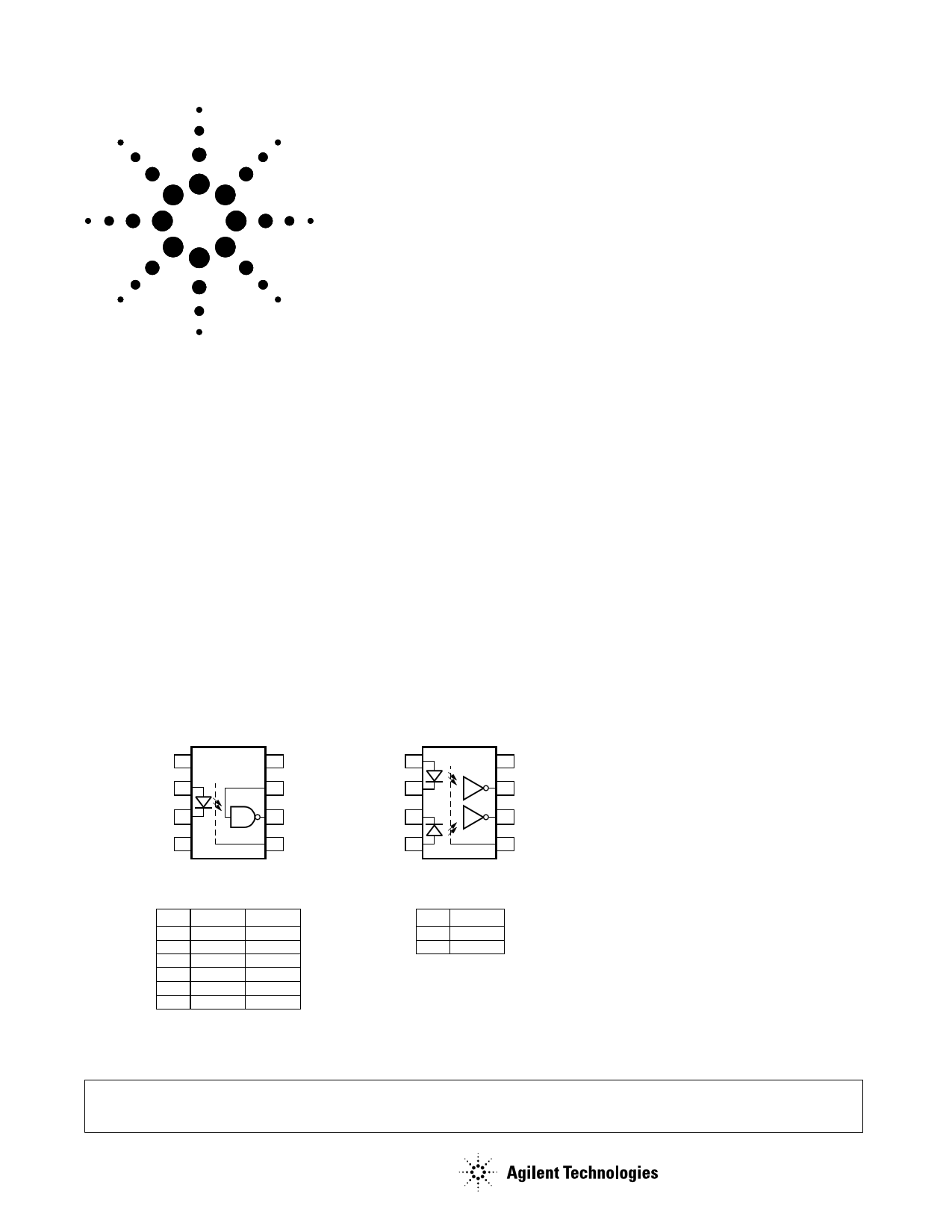
Functional Diagram
HCPL-260L/060L
NC 1
8 VCC
ANODE 2
7 VE
CATHODE 3
6 VO
NC 4
SHIELD
5 GND
HCPL-263L/063L
ANODE 1 1
8 VCC
CATHODE 1 2
7 VO1
CATHODE 2 3
6 VO2
ANODE 2 4
5 GND
SHIELD
Features
• Low power consumption
• 15 kV/µs minimum Common Mode
Rejection (CMR) at VCM = 50 V
• High speed: 15 MBd typical
• LVTTL/LVCMOS compatible
• Low input current capability:
5 mA
• Guaranteed AC and DC performance
over temperature: –40˚C to +85˚C
• Available in 8-pin DIP, SOIC-8
• Strobable output (single channel
products only)
• Safety approvals; UL, CSA, VDE 0884
Applications
• Isolated line receiver
• Computer-peripheral interfaces
• Microprocessor system interfaces
• Digital isolation for A/D, D/A
conversion
• Switching power supply
• Instrument input/output isolation
• Ground loop elimination
• Pulse transformer replacement
• Field buses
TRUTH TABLE
(POSITIVE LOGIC)
LED
ON
OFF
ON
OFF
ON
OFF
ENABLE
H
H
L
L
NC
NC
OUTPUT
L
H
H
H
L
H
TRUTH TABLE
(POSITIVE LOGIC)
LED
ON
OFF
OUTPUT
L
H
A 0.1 µF bypass capacitor must be connected between pins 5 and 8.
CAUTION: It is advised that normal static precautions be taken in handling and assembly of this component to prevent
damage and/or degradation which may be induced by ESD.
1 page 
Insulation and Safety Related Specifications
Parameter
Minimum External Air
Gap (External Clearance)
Minimum External Tracking
(External Creepage)
Minimum Internal Plastic
Gap (Internal Clearance)
Symbol
L (101)
L (102)
8-Pin DIP
(300 Mil)
Value
7.1
7.4
0.08
Tracking Resistance
(Comparative Tracking
Index)
Isolation Group
CTI
200
IIIa
SO-8
Value
4.9
4.8
0.08
200
IIIa
Units
mm
mm
mm
Volts
Conditions
Measured from input terminals to output
terminals, shortest distance through air.
Measured from input terminals to output
terminals, shortest distance path along body.
Through insulation distance, conductor to
conductor, usually the direct distance
between the photoemitter and photodetector
inside the optocoupler cavity.
DIN IEC 112/VDE 0303 Part 1
Material Group (DIN VDE 0110, 1/89, Table 1)
VDE 0884 Insulation Related Characteristics
Description
Installation classification per DIN VDE 0110/1.89, Table 1
for rated mains voltage ≤ 150 V rms
for rated mains voltage ≤ 300 V rms
for rated mains voltage ≤ 600 V rms
Climatic Classification
Pollution Degree (DIN VDE 0110/1.89)
Maximum Working Insulation Voltage
Input to Output Test Voltage, Method b*
VIORM x 1.875 = VPR, 100% Production Test
with tm = 1 sec, Partial Discharge < 5 pC
Input to Output Test Voltage, Method a*
VIORM x 1.5 = VPR, Type and Sample Test,
tm = 60 sec, Partial Discharge < 5 pC
Highest Allowable Overvoltage*
(Transient Overvoltage, tini = 10 sec)
Safety Limiting Values
(Maximum values allowed in the event of a failure,
also see Figure 16, Thermal Derating curve.)
Case Temperature
Input Current
Output Power
Insulation Resistance at TS, VIO = 500 V
Symbol
VIORM
VPR
PDIP Option 060 SO-8 Option 60
I-IV
I-III
55/85/21
2
630
I-IV
I-III
I-II
55/85/21
2
566
1181 1063
VPR
VIOTM
945
6000
849
4000
TS
IS,INPUT
PS,OUTPUT
RS
175
230
600
≥ 109
150
150
600
≥ 109
Units
Vpeak
Vpeak
Vpeak
Vpeak
˚C
mA
mW
Ω
*Refer to the front of the optocoupler section of the current catalog, under Product Safety Regulations section (VDE 0884), for a detailed description.
Note: Isolation characteristics are guaranteed only within the safety maximum ratings which must be ensured by protective circuits in application.
5
5 Page 
150
VCC = 3.3 V
IF = 7.5 mA
120
tPLH , RL = 350 Ω
90
60
tPHL , RL = 350 Ω
30
0
-60 -40 -20 0 20 40 60 80 100
TA – TEMPERATURE – °C
Figure 7. Typical propagation delay vs.
temperature.
50
VCC = 3.3 V
IF = 7.5 mA
40
30
RL = 350 Ω
20
10
0
-60 -40 -20 0 20 40 60 80 100
TA – TEMPERATURE – °C
Figure 8. Typical pulse width distortion vs.
temperature.
PULSE GEN.
ZO = 50 Ω
tf = tr = 5 ns
INPUT VE
MONITORING NODE
7.5 mA
IF
1
2
3
4
VCC 8
7
6
5
GND
+3.3 V
0.1 µF
BYPASS
*CL
RL
OUTPUT VO
MONITORING
NODE
INPUT
VE
OUTPUT
VO
tEHL
tELH
3.0 V
1.5 V
1.5 V
*CL IS APPROXIMATELY 15 pF WHICH INCLUDES
PROBE AND STRAY WIRING CAPACITANCE.
Figure 9. Test circuit for tEHL and tELH.
IF
B
A
VFF
SINGLE CHANNEL
1 VCC 8
27
36
4 GND 5
IF
+3.3 V
0.1 µF
BYPASS
RL
OUTPUT VO
MONITORING
NODE
B
A
VFF
DUAL CHANNEL
1 VCC 8
27
36
4 GND 5
VCM
+–
PULSE
GENERATOR
ZO = 50 Ω
VCM
0V
VO 3.3 V
VO 0.5 V
VCM (PEAK)
SWITCH AT A: IF = 0 mA
VO (MIN.)
SWITCH AT B: IF = 7.5 mA
VO (MAX.)
CMH
VCM
+–
PULSE
GENERATOR
ZO = 50 Ω
CML
RL
0.1 µF
BYPASS
+3.3 V
OUTPUT VO
MONITORING
NODE
Figure 10. Test circuit for common mode transient immunity and typical waveforms.
11
11 Page | ||
| Páginas | Total 15 Páginas | |
| PDF Descargar | [ Datasheet HCPL-063L.PDF ] | |
Hoja de datos destacado
| Número de pieza | Descripción | Fabricantes |
| HCPL-0630 | High Speed TTL Compatible Optocouplers | HP |
| HCPL-0630 | High Speed TTL Compatible Optocouplers | Avago |
| HCPL-0631 | High Speed TTL Compatible Optocouplers | HP |
| HCPL-0631 | High Speed TTL Compatible Optocouplers | Avago |
| Número de pieza | Descripción | Fabricantes |
| SLA6805M | High Voltage 3 phase Motor Driver IC. |
Sanken |
| SDC1742 | 12- and 14-Bit Hybrid Synchro / Resolver-to-Digital Converters. |
Analog Devices |
|
DataSheet.es es una pagina web que funciona como un repositorio de manuales o hoja de datos de muchos de los productos más populares, |
| DataSheet.es | 2020 | Privacy Policy | Contacto | Buscar |