|
|
|
PDF IRF1324PbF Data sheet ( Hoja de datos )
| Número de pieza | IRF1324PbF | |
| Descripción | Power MOSFET ( Transistor ) | |
| Fabricantes | International Rectifier | |
| Logotipo | ||
Hay una vista previa y un enlace de descarga de IRF1324PbF (archivo pdf) en la parte inferior de esta página. Total 8 Páginas | ||
|
No Preview Available !
Applications
l High Efficiency Synchronous Rectification in SMPS
l Uninterruptible Power Supply
l High Speed Power Switching
l Hard Switched and High Frequency Circuits
G
Benefits
l Improved Gate, Avalanche and Dynamic dV/dt
Ruggedness
l Fully Characterized Capacitance and Avalanche
SOA
l Enhanced body diode dV/dt and dI/dt Capability
l Lead-Free
PD - 96199A
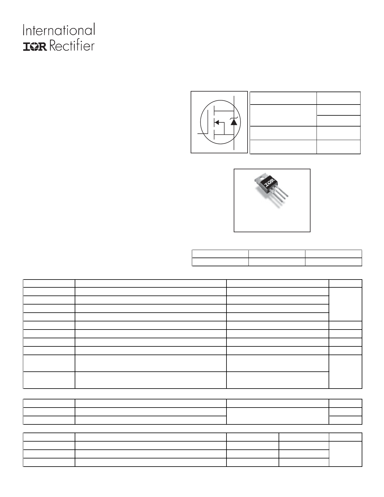
IRF1324PbF
HEXFET® Power MOSFET
D VDSS
RDS(on) typ.
max.
ID (Silicon Limited)
24V
1.2m:
1.5m:
c353A
S ID (Package Limited) 195A
GDS
TO-220AB
IRF1324PbF
G
Gate
Absolute Maximum Ratings
Symbol
Parameter
ID @ TC = 25°C
ID @ TC = 100°C
ID @ TC = 25°C
IDM
PD @TC = 25°C
Continuous Drain Current, VGS @ 10V (Silicon Limited)
Continuous Drain Current, VGS @ 10V (Silicon Limited)
Continuous Drain Current, VGS @ 10V (Wire Bond Limited)
dPulsed Drain Current
Maximum Power Dissipation
Linear Derating Factor
VGS
dv/dt
Gate-to-Source Voltage
fPeak Diode Recovery
TJ
TSTG
Operating Junction and
Storage Temperature Range
Soldering Temperature, for 10 seconds
(1.6mm from case)
Avalanche Characteristics
EAS (Thermally limited)
IAR
EAR
eSingle Pulse Avalanche Energy
ÃdAvalanche Current
gRepetitive Avalanche Energy
Thermal Resistance
Symbol
RθJC
RθCS
RθJA
Parameter
jJunction-to-Case
Case-to-Sink, Flat Greased Surface
jJunction-to-Ambient
www.irf.com
D
Drain
Max.
353
249
195
1412
300
2.0
± 20
0.46
-55 to + 175
300
S
Source
Units
A
W
W/°C
V
V/ns
°C
270
See Fig. 14, 15, 22a, 22b
Typ.
–––
0.50
–––
Max.
0.50
–––
62
mJ
A
mJ
Units
°C/W
1
09/24/09
1 page 
IRF1324PbF
1
D = 0.50
0.1
0.01
0.20
0.10
0.05
0.02
0.01
0.001
1E-006
SINGLE PULSE
( THERMAL RESPONSE )
τJ τJ
τ1 τ1
R1R1
CiC= iτi/Ri/iRi
R2R2
τ2 τ2
R3R3
τ3 τ3
1E-005
0.0001
0.001
t1 , Rectangular Pulse Duration (sec)
R4R4
τCτ
Ri (°C/W)
0.0125
0.0822
τi (sec)
0.000008
0.000078
τ4τ4 0.2019 0.001110
0.2036 0.007197
Notes:
1. Duty Factor D = t1/t2
2. Peak Tj = P dm x Zthjc + Tc
0.01
0.1
Fig 13. Maximum Effective Transient Thermal Impedance, Junction-to-Case
1000
Duty Cycle = Single Pulse
0.01
100
0.05
0.10
Allowed avalanche Current vs avalanche
pulsewidth, tav, assuming ∆Tj = 150°C and
Tstart =25°C (Single Pulse)
10
Allowed avalanche Current vs avalanche
pulsewidth, tav, assuming ∆Τ j = 25°C and
Tstart = 150°C.
1
1.0E-06
1.0E-05
1.0E-04
1.0E-03
tav (sec)
Fig 14. Typical Avalanche Current vs.Pulsewidth
1.0E-02
1.0E-01
www.irf.com
5
5 Page | ||
| Páginas | Total 8 Páginas | |
| PDF Descargar | [ Datasheet IRF1324PbF.PDF ] | |
Hoja de datos destacado
| Número de pieza | Descripción | Fabricantes |
| IRF1324PbF | Power MOSFET ( Transistor ) | International Rectifier |
| Número de pieza | Descripción | Fabricantes |
| SLA6805M | High Voltage 3 phase Motor Driver IC. |
Sanken |
| SDC1742 | 12- and 14-Bit Hybrid Synchro / Resolver-to-Digital Converters. |
Analog Devices |
|
DataSheet.es es una pagina web que funciona como un repositorio de manuales o hoja de datos de muchos de los productos más populares, |
| DataSheet.es | 2020 | Privacy Policy | Contacto | Buscar |