|
|
|
PDF ISL12008 Data sheet ( Hoja de datos )
| Número de pieza | ISL12008 | |
| Descripción | Real Time Clock | |
| Fabricantes | Intersil | |
| Logotipo | ||
Hay una vista previa y un enlace de descarga de ISL12008 (archivo pdf) en la parte inferior de esta página. Total 19 Páginas | ||
|
No Preview Available !
ISL12008
® I2C Real Time Clock with Battery Backup
Data Sheet
September 26, 2008
FN6690.1
Low Power RTC with Battery ReSeal™
Function
The ISL12008 device is a low power real time clock/calendar
that is pin compatible and functionally equivalent to the
ST M41T00S and Maxim DS1340 with timing and crystal
compensation. The device additionally provides power-fail
indicator, software alarm and intelligent battery backup.
The oscillator uses an external, low-cost 32.768kHz crystal.
The real time clock tracks time with separate registers for
hours, minutes, and seconds. The device has calendar
registers for date, month, year and day of the week. The
calendar is accurate through 2099, with automatic leap year
correction.
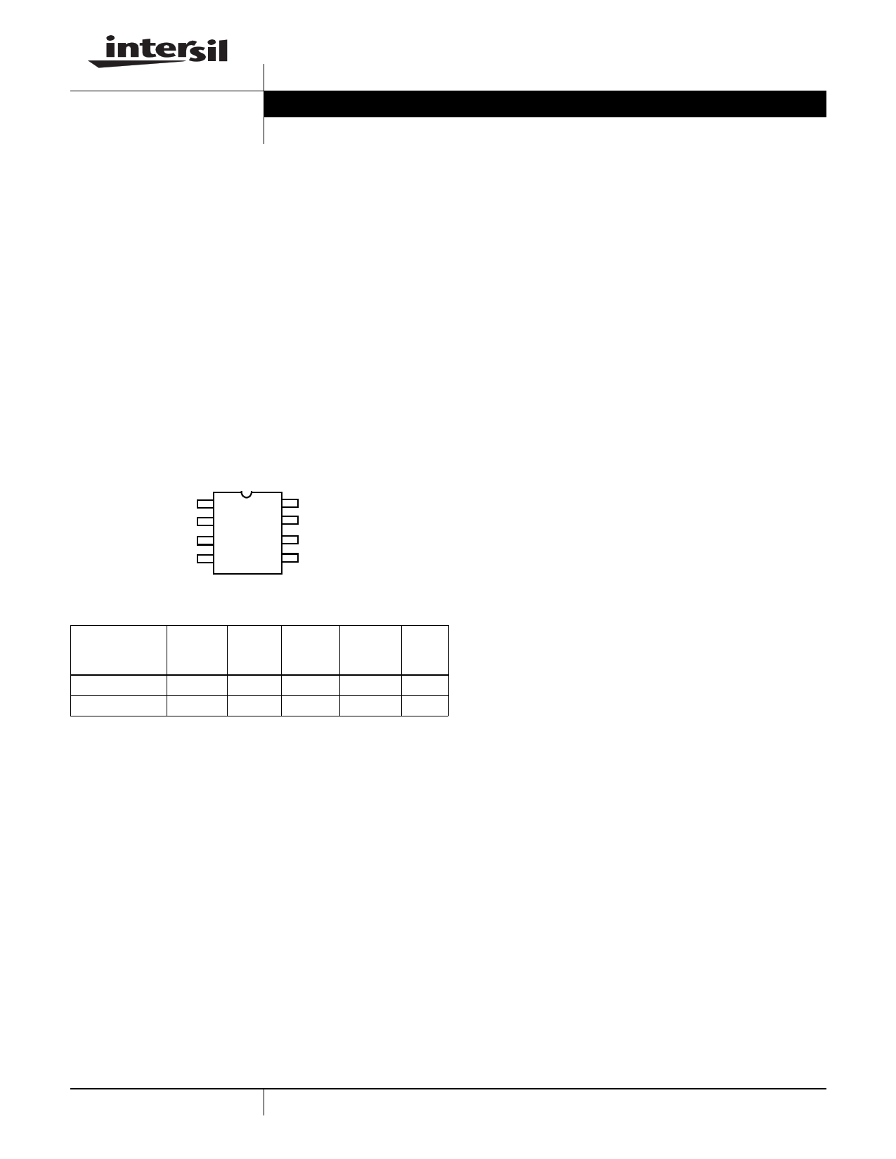
Pinout
X1
X2
VBAT
GND
ISL12008
(8 LD SOIC)
TOP VIEW
18
27
36
45
VDD
FT/OUT
SCL
SDA
Ordering Information
PART
NUMBER
(Note)
VDD TEMP.
PART RANGE RANGE PACKAGE PKG.
MARKING (V)
(°C) (Pb-free) DWG. #
ISL12008IB8Z 12008 IBZ 2.7 to 5.5 -40 to +85 8 Ld SOIC M8.15
ISL12008IB8Z-T* 12008 IBZ 2.7 to 5.5 -40 to +85 8 Ld SOIC M8.15
*Please refer to TB347 for details on reel specifications.
NOTE: These Intersil Pb-free plastic packaged products employ special
Pb-free material sets, molding compounds/die attach materials, and
100% matte tin plate plus anneal (e3 termination finish, which is RoHS
compliant and compatible with both SnPb and Pb-free soldering
operations). Intersil Pb-free products are MSL classified at Pb-free peak
reflow temperatures that meet or exceed the Pb-free requirements of
IPC/JEDEC J STD-020.
Features
• Pin Compatible to ST M41T00S and Maxim DS1340
• Functionality Equivalent to ST M41T00S and Maxim
DS1340
• Real Time Clock/Calendar
- Tracks Time in Hours, Minutes, Seconds and
Sub-seconds
- Day of the Week, Day, Month, and Year
• 512Hz Frequency Outputs for On-Chip Crystal
Compensation
• Software Alarm
- Settable to the Second, Minute, Hour, Day of the Week,
Day, or Month
• Automatic Low-Drop Battery Switch for Longest Backup
Life
• Power Failure Detection
• Battery ReSeal™ for Long Shelf Life
• I2C Bus™
- 400kHz Data Transfer Rate
• 800nA Battery Supply Current
• Small Package Option
- 8 Ld SOIC
• Pb-Free (RoHS Compliant)
Applications
• Utility Meters
• HVAC Equipment
• Audio/Video Components
• Set-Top Box/Television
• Modems
• Network Routers, Hubs, Switches, Bridges
• Cellular Infrastructure Equipment
• Fixed Broadband Wireless Equipment
• Pagers/PDA
• POS Equipment
• Test Meters/Fixtures
• Office Automation (Copiers, Fax)
• Home Appliances
• Computer Products
• Other Industrial/Medical/Automotive
.
1 CAUTION: These devices are sensitive to electrostatic discharge; follow proper IC Handling Procedures.
1-888-INTERSIL or 1-888-468-3774 | Intersil (and design) is a registered trademark of Intersil Americas Inc.
ReSeal™
is
a
trademark
owned
byInteI2rsCil
Americas Inc.Copyright Intersil Americas Inc. 2008. All Rights Reserved
Bus™ is a trademark owned by NXP Semiconductors Netherlands, B.V.
All other trademarks mentioned are the property of their respective owners.
1 page 
ISL12008
SDA vs SCL Timing
tF
tHIGH
tLOW
tR
SCL
tSU:STA
SDA
(INPUT TIMING)
SDA
(OUTPUT TIMING)
tSU:DAT
tHD:STA
tHD:DAT
tAA tDH
Symbol Table
WAVEFORM
INPUTS
Must be steady
OUTPUTS
Will be steady
May change
from LOW
to HIGH
May change
from HIGH
to LOW
Don’t Care:
Changes Allowed
Will change
from LOW
to HIGH
Will change
from HIGH
to LOW
Changing:
State Not Known
N/A Center Line is
High Impedance
tSU:STO
tBUF
5 FN6690.1
September 26, 2008
5 Page 
ISL12008
LEAP YEARS
Leap years add the day February 29 and are defined as those
years that are divisible by 4. Years divisible by 100 are not leap
years, unless they are also divisible by 400. This means that
the year 2000 is a leap year, the year 2100 is not. The
ISL12008 does not correct for the leap year in the year 2100.
Control and Status Registers
Addresses [07h to 0Bh]
The Control and Status Registers consist of the Status
Register, Interrupt and Alarm Register, Analog Trimming and
Digital Trimming Registers.
Status Register (SR) [Address 0Bh]
The Status Register is located in the memory map at
address 0Bh. This is a volatile register that provides either
control or status of RTC failure, battery mode, alarm trigger,
crystal oscillator status, ReSeal™ and auto reset of status
bits.
TABLE 2. STATUS REGISTER (SR)
ADDR 7
6
5 4 3 21 0
0Bh ARST 0 RESEAL 0
0 ALM BAT RTCF
Default 0
0
0 0 0 01 1
REAL TIME CLOCK FAIL BIT (RTCF)
This bit is set to a “1” after a total power failure. This is a read
only bit that is set by hardware (ISL12008 internally) when
the device powers up after having lost all power to the device
(both VDD and VBAT go to 0V). The bit is set regardless of
whether VDD or VBAT is applied first. The loss of only one of
the supplies does not set the RTCF bit to “1”. On power-up
after a total power failure, all registers are set to their default
states and the clock will not increment until at least one byte
is written to the clock register. The first valid write to the RTC
section after a complete power failure resets the RTCF bit to
“0” (writing one byte is sufficient).
BATTERY BIT (BAT)
This bit is set to a “1” when the device enters battery backup
mode. This bit can be reset either manually by the user or
automatically reset by enabling the auto-reset bit (see ARST
bit). A write to this bit in the SR can only set it to “0”, not “1”.
ALARM BIT (ALM)
These bits announce if the alarm matches the real time
clock. If there is a match, the respective bit is set to “1”. This
bit can be manually reset to “0” by the user or automatically
reset by enabling the auto-reset bit (see ARST bit). A write to
this bit in the SR can only set it to “0”, not “1”.
NOTE: An alarm bit that is set by an alarm occurring during an SR
read operation will remain set after the read operation is complete.
ReSeal (RESEAL)
The ReSeal™ enables the device enter into the InterSeal™
Battery Saver mode after manufacture testing for board
functionality. The factory default setting of this bit is “0”. The
RESEAL must be set to “0” to enable the battery function
during normal operation or full functional testing. To use the
ReSeal function, simply set RESEAL bit to “1” after the
testing is completed. It will enable the InterSeal™ Battery
Saver mode and prevents battery current drain before it is
first used.
AUTO RESET ENABLE BIT (ARST)
This bit enables/disables the automatic reset of the BAT,
ALM and TMR status bits only. When ARST bit is set to “1”,
these status bits are reset to “0” after a valid read of the
respective status register (with a valid STOP condition).
When the ARST is cleared to “0”, the user must manually
reset the BAT and ALM bits.
Interrupt Control Register (INT) [Address 08h]
TABLE 3. INTERRUPT CONTROL REGISTER (INT)
ADDR 7 6
5
4 3210
08h 0 ALME LPMODE 0
0000
Default 0 0
0
0 0000
LOW POWER MODE BIT (LPMODE)
This bit enables/disables low power mode. With
LPMODE = “0”, the device will be in normal mode and the
VBAT supply will be used when VDD < VBAT - VBATHYS and
VDD < VTRIP. With LPMODE = “1”, the device will be in low
power mode and the VBAT supply will be used when
VDD < VBAT - VBATHYS. There is a supply current saving of
about 600nA when using LPMODE = “1” with VDD = 5V.
(See “Typical Performance Curves” on page 6: IDD vs VCC
with LPMODE ON and OFF.)
ALARM ENABLE BIT (ALME)
This bit enables/disables the alarm function. When the ALME
bit is set to “1”, the alarm function is enabled. When the ALME
bit is cleared to “0”, the alarm function is disabled. ALME bit is
set to “0” at power-up.
Oscillator Fail Register (OF) [Address 09h]
TABLE 4. INTERRUPT CONTROL REGISTER (INT)
ADDR 7
6543210
09h OF 0 0 0 0 0 0 0
Default 1
0000000
OSCILLATOR FAIL BIT (OF)
This bit is set to a “1” when the X1 pin has no oscillation.
This bit can be reset when the X1 has crystal oscillation and
a write to “0”. This bit can only be written as “0” and not as a
“1”. The OF bit is set to “1” at power up from a complete
power down (VDD and VBAT are removed). Address 1, bit 7
11 FN6690.1
September 26, 2008
11 Page | ||
| Páginas | Total 19 Páginas | |
| PDF Descargar | [ Datasheet ISL12008.PDF ] | |
Hoja de datos destacado
| Número de pieza | Descripción | Fabricantes |
| ISL12008 | Real Time Clock | Intersil |
| Número de pieza | Descripción | Fabricantes |
| SLA6805M | High Voltage 3 phase Motor Driver IC. |
Sanken |
| SDC1742 | 12- and 14-Bit Hybrid Synchro / Resolver-to-Digital Converters. |
Analog Devices |
|
DataSheet.es es una pagina web que funciona como un repositorio de manuales o hoja de datos de muchos de los productos más populares, |
| DataSheet.es | 2020 | Privacy Policy | Contacto | Buscar |